Rear panel fits!
The rear panel arrived from Front Panel Express today. It fits perfectly! I nailed the measurements. So go ahead an use both the front and rear .fpd panel CAD files, and the measurements spreadsheet with the raw measurements for self-drilling, out at the Google Drive link in the "panels" folder.
Here are some photos of the panel and attaching it to the four voltage regulators with the TO-220 insulators in the BOM. I've gone up one notch on the camera here for some better resolution.
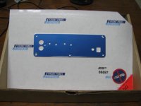
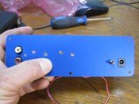
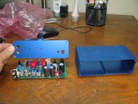
* The first photo shows the panel as it came in the box from Front Panel Express. I've never used these folks before. I'm impressed with how they have it packed. For this particular panel to test the measurements I did not add any text labeling to the panel. The one out at the Google Drive link does have the text added.
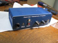
* Next shows the panel, rear of the ODA, and the B4-080 case. The panel used the "blue" anodization option in FPD. The the shade of blue matches the B4-080 reasonably well.
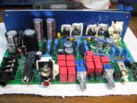
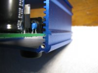
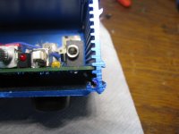
* Next is the panel over the switch, power jack, and RCA jacks showing the alignment of the voltage regulator holes with the panel. It fits! When you solder in the regulators make sure they are all the way down on the PC board. Then everything will line up fine like this. Notice that the on/off switch acts like a locator on the right of the panel and the RCA jack mounting screw hole is a locator on the left.
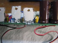
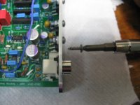
* The next 4 photos show how the heat sink grease and mica washers (from the TO-220 mounting kits in the BOM, one for each regulator) are attached. First just smear some zinc oxide heat sink grease over the tabs on all 4 voltage regulators.
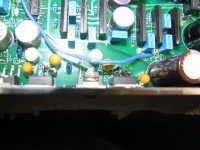
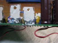
In the second photo here notice how the standard mica washer is too long and hits the PC board. This is by design. The regulator leads have two sizes. By pushing it all the way down until the larger size hits and is flush with the PC board like this you will get the same exactly height for the regulator hole every time. Easy. If I left the LM317/337 leads long to match up with the greater height of the LDO voltage regulator tabs it would have become hard to get the height correct. The next shot shows how I've just snipped the bottom of the mica insulator above the 2 holes using flush cutters. Then the final shot shows the mica insulators stuck to the grease on all 4 regulators, the holes in the mica lined up with the holes in the regulators (tip: stick the tip of needle nose pliers in to line them both right up) then more grease applied to the outside of the mica washer where the back panel will mate.
Note that the tabs on the LM317 and LM337 pre-regulators are also half as thick as those on the LT1963A aqnd LT3015 LDOs. The LDOs sit higher because of the 5 leg arrangement. The difference in tab thickness is why I have 10mm long bolts in the mounting kit. 8mm would be OK for the thinner tabs, but not for the thicker LDO tabs.
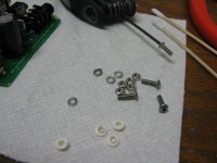
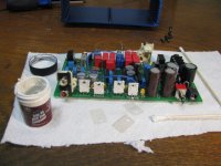
* The next three photos show attaching the hardware and nylon insulating washer from the TO-220 mounting kit. The kit in the BOM comes with 4-40 hardware. With the mounting kit I have in the vendor thread you can toss the 4-40 bolt and nut (keep the mica and nylon washers of course) and use the stainless steel button head stuff (what I'm using in these photos). The button head bolts take a 2mm metric allen wrench. That one I'm using in the photo is a set that is $2 at Harbor Freight tools here in the US. Most hardware stores have something similar. Be sure to get the metric allen wrenches though.
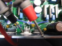
The first photo shows the pile of parts. Next shows one fully assembled with the bolt through the panel and the insulating washer, lockwasher, and nut on the other side. I find it is handy to keep a finger on the nut and washers on the back to push them against the panel (and the insulating nylon washer properly through the hole), then screw the bolt from the front. Keep the nuts jsut hand tight until all 4 are in, then put some needle nose on the nuts and tighten them up a bit - but not too much, don't want to punch through the mica washer. Just slightly firm.
Finally I do a resistance check between the panel and the tab to make sure everything was aligned properly. Interestingly enough, if you measure between the panel and the bolt you also may register nearly open, even though the bolt head touches the panel. That is due to the insulating properties of the blue anodization, which is why I have that lower left case screw corner slightly countersunk. That cuts through the anodization to provide a good electrical connection to ground the panel.
The rear panel arrived from Front Panel Express today. It fits perfectly! I nailed the measurements.
So go ahead an use both the front and rear .fpd panel CAD files, and the measurements spreadsheet with the raw measurements for self-drilling, out at the Google Drive link in the "panels" folder. Here are some photos of the panel and attaching it to the four voltage regulators with the TO-220 insulators in the BOM. I've gone up one notch on the camera here for some better resolution.
* The first photo shows the panel as it came in the box from Front Panel Express. I've never used these folks before. I'm impressed with how they have it packed. For this particular panel to test the measurements I did not add any text labeling to the panel. The one out at the Google Drive link does have the text added.
* Next shows the panel, rear of the ODA, and the B4-080 case. The panel used the "blue" anodization option in FPD. The the shade of blue matches the B4-080 reasonably well.
* Next is the panel over the switch, power jack, and RCA jacks showing the alignment of the voltage regulator holes with the panel. It fits! When you solder in the regulators make sure they are all the way down on the PC board. Then everything will line up fine like this. Notice that the on/off switch acts like a locator on the right of the panel and the RCA jack mounting screw hole is a locator on the left.
* The next 4 photos show how the heat sink grease and mica washers (from the TO-220 mounting kits in the BOM, one for each regulator) are attached. First just smear some zinc oxide heat sink grease over the tabs on all 4 voltage regulators.
In the second photo here notice how the standard mica washer is too long and hits the PC board. This is by design. The regulator leads have two sizes. By pushing it all the way down until the larger size hits and is flush with the PC board like this you will get the same exactly height for the regulator hole every time. Easy. If I left the LM317/337 leads long to match up with the greater height of the LDO voltage regulator tabs it would have become hard to get the height correct. The next shot shows how I've just snipped the bottom of the mica insulator above the 2 holes using flush cutters. Then the final shot shows the mica insulators stuck to the grease on all 4 regulators, the holes in the mica lined up with the holes in the regulators (tip: stick the tip of needle nose pliers in to line them both right up) then more grease applied to the outside of the mica washer where the back panel will mate.
Note that the tabs on the LM317 and LM337 pre-regulators are also half as thick as those on the LT1963A aqnd LT3015 LDOs. The LDOs sit higher because of the 5 leg arrangement. The difference in tab thickness is why I have 10mm long bolts in the mounting kit. 8mm would be OK for the thinner tabs, but not for the thicker LDO tabs.
* The next three photos show attaching the hardware and nylon insulating washer from the TO-220 mounting kit. The kit in the BOM comes with 4-40 hardware. With the mounting kit I have in the vendor thread you can toss the 4-40 bolt and nut (keep the mica and nylon washers of course) and use the stainless steel button head stuff (what I'm using in these photos). The button head bolts take a 2mm metric allen wrench. That one I'm using in the photo is a set that is $2 at Harbor Freight tools here in the US. Most hardware stores have something similar. Be sure to get the metric allen wrenches though.
The first photo shows the pile of parts. Next shows one fully assembled with the bolt through the panel and the insulating washer, lockwasher, and nut on the other side. I find it is handy to keep a finger on the nut and washers on the back to push them against the panel (and the insulating nylon washer properly through the hole), then screw the bolt from the front. Keep the nuts jsut hand tight until all 4 are in, then put some needle nose on the nuts and tighten them up a bit - but not too much, don't want to punch through the mica washer. Just slightly firm.
Finally I do a resistance check between the panel and the tab to make sure everything was aligned properly. Interestingly enough, if you measure between the panel and the bolt you also may register nearly open, even though the bolt head touches the panel. That is due to the insulating properties of the blue anodization, which is why I have that lower left case screw corner slightly countersunk. That cuts through the anodization to provide a good electrical connection to ground the panel.
Attachments
-
 IMG_2507.JPG39.3 KB · Views: 397
 -
 IMG_2523.JPG99.4 KB · Views: 128
 -
 IMG_2520.JPG116 KB · Views: 118
 -
 IMG_2516.JPG87.1 KB · Views: 109
 -
 IMG_2515.JPG102.2 KB · Views: 114
 -
 IMG_2514.JPG87.8 KB · Views: 110
 -
 IMG_2513.JPG85.9 KB · Views: 381
 -
 IMG_2512.JPG109.3 KB · Views: 382
 -
 IMG_2510.JPG46.7 KB · Views: 384
 -
 IMG_2509.JPG63.6 KB · Views: 399
Last edited:
rear panel, continued...
More photos of attaching the rear panel and inserting into the B4-080 case.
* The first photo shows the last remaining screw in the rear panel, the #4 truss head screw that comes with my mounting kit, which screws into the nylon RCA jack through the small hole in the panel.
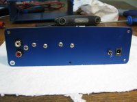
* The next two photos shows both sides of the entire completed rear panel. I've wiped the excess zinc oxide grease from the outside of the rear panel, but probably won't bother with the inside.
* The next photo is a reminder that the ODA board goes in the second slot up from the bottom. That is because of the extrusion that runs down the center at the bottom for the bottom center front and rear panel screws. So there is actually a pretty good amount of space in the ODA between the bottom of the board and the bottom of the case. Along with mounting the ODAC above a board in the case top slot, you could probably wrap one up and put under the PC board, as folks have done with NwAvGuy's O2 headamp. I would recommend the board in the top slot approach though to keep the noisy digital stuff on the ODAC far away from the sensitive analog ODA parts.
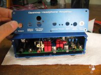
* The next photo shows the amount of space I've left between the sides of the case and the parts and traces on the PC board. 3mm to the parts and 5mm to the traces to stay away from side extrusions on the case. I probably overdid it if anything from the looks of things here. That was a reaction to NwAvGuy not leaving enough space to the sides, and especially to that case rail under the edges of the board (that part leads shorted against if not trimmed close). No chance of that happening here.
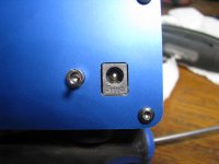
* The next one just makes me smile. What are the odds of getting that spacing measurements around the DC power jack that even? I really like the way this has turned out, to have that jack forward and through the rectangular panel hole. Looks more professional and zero chance of the power adaptor barrel touching the panel.
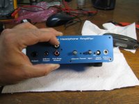
* The final 3 photos show the front panel installed. This is a front panel I had left over from the previous ODA version. Fits since no changes have happened to the front of the board. The first photo is without the knobs and nuts installed. The next photo has the knobs and nuts. I'm doing some sleight of hand with my finger here. Normally the truss head screw into the RCA jack (pre-amp out here on the front) would pull those jacks forward and flush against the panel. Since the screw is out I'm doing it with my finger for the photo. The final shot shows the cover off.
Remember how the whole grounding thing works here from the previous ODA version. I have the holes around the 3.5mm input jack and the lower right case screw countersunk to cut through the (insulating ) blue anodization. The 3.5mm jack nut then single point grounds the panel when installed, The lower right case screw single point grounds the case to the panel. Then in the back the similar case screw does the same for the rear panel. Just like that you have a real Faraday cage with minimal circulating ground loops.
The output jacks don't touch the front panel on purpose (the 1/4" is plastic for this reason). As far as the headphones are concerned the ground terminal on either jack is their ground and not the system star ground in the power supply section (although the output jack grounds do direclty star ground to the system star ground point - keep reading). The tiny difference this makes figures into how I managed to get the DC output offset so low. In the layout you can see that the DC output offset null circuit is the one thing on the board that does not reference back to the system star ground directly, but rather tp the headphone jack ground terminal before it in turn stars to the system star ground. That is because the headphone currents gonig back to star ground can cause 500uV or more drops across the PC board traces that would add to the DC output offset, and we are shooting for lower than 100 micovolts here. By referring the DC output offset null circuit back to the output jack ground those trace drops are moot and you get super low output DC offset numbers. Low enough to read "0Vdc" on a DMM that has only 1mV minimum resolution on its Vdc range.
Back to the panel, that is also why the large hole around the 3.5mm output jack, to make sure it does not touch the panel. Again no smoke or sparks if it did, it would just negate a few 100's of microvolts of DC offset nulling abilty.
It is less of a big deal if the shafts of the volume pot or gain switch touch, but I've left a fairly big hole around those too.
More photos of attaching the rear panel and inserting into the B4-080 case.
* The first photo shows the last remaining screw in the rear panel, the #4 truss head screw that comes with my mounting kit, which screws into the nylon RCA jack through the small hole in the panel.
* The next two photos shows both sides of the entire completed rear panel.
I've wiped the excess zinc oxide grease from the outside of the rear panel, but probably won't bother with the inside.* The next photo is a reminder that the ODA board goes in the second slot up from the bottom. That is because of the extrusion that runs down the center at the bottom for the bottom center front and rear panel screws. So there is actually a pretty good amount of space in the ODA between the bottom of the board and the bottom of the case. Along with mounting the ODAC above a board in the case top slot, you could probably wrap one up and put under the PC board, as folks have done with NwAvGuy's O2 headamp. I would recommend the board in the top slot approach though to keep the noisy digital stuff on the ODAC far away from the sensitive analog ODA parts.
* The next photo shows the amount of space I've left between the sides of the case and the parts and traces on the PC board. 3mm to the parts and 5mm to the traces to stay away from side extrusions on the case. I probably overdid it if anything from the looks of things here.
That was a reaction to NwAvGuy not leaving enough space to the sides, and especially to that case rail under the edges of the board (that part leads shorted against if not trimmed close). No chance of that happening here.* The next one just makes me smile. What are the odds of getting that spacing measurements around the DC power jack that even?
I really like the way this has turned out, to have that jack forward and through the rectangular panel hole. Looks more professional and zero chance of the power adaptor barrel touching the panel.* The final 3 photos show the front panel installed. This is a front panel I had left over from the previous ODA version. Fits since no changes have happened to the front of the board. The first photo is without the knobs and nuts installed. The next photo has the knobs and nuts. I'm doing some sleight of hand with my finger here. Normally the truss head screw into the RCA jack (pre-amp out here on the front) would pull those jacks forward and flush against the panel. Since the screw is out I'm doing it with my finger for the photo. The final shot shows the cover off.
Remember how the whole grounding thing works here from the previous ODA version. I have the holes around the 3.5mm input jack and the lower right case screw countersunk to cut through the (insulating ) blue anodization. The 3.5mm jack nut then single point grounds the panel when installed, The lower right case screw single point grounds the case to the panel. Then in the back the similar case screw does the same for the rear panel. Just like that you have a real Faraday cage with minimal circulating ground loops.
The output jacks don't touch the front panel on purpose (the 1/4" is plastic for this reason). As far as the headphones are concerned the ground terminal on either jack is their ground and not the system star ground in the power supply section (although the output jack grounds do direclty star ground to the system star ground point - keep reading). The tiny difference this makes figures into how I managed to get the DC output offset so low. In the layout you can see that the DC output offset null circuit is the one thing on the board that does not reference back to the system star ground directly, but rather tp the headphone jack ground terminal before it in turn stars to the system star ground. That is because the headphone currents gonig back to star ground can cause 500uV or more drops across the PC board traces that would add to the DC output offset, and we are shooting for lower than 100 micovolts here. By referring the DC output offset null circuit back to the output jack ground those trace drops are moot and you get super low output DC offset numbers. Low enough to read "0Vdc" on a DMM that has only 1mV minimum resolution on its Vdc range.
Back to the panel, that is also why the large hole around the 3.5mm output jack, to make sure it does not touch the panel. Again no smoke or sparks if it did, it would just negate a few 100's of microvolts of DC offset nulling abilty.
It is less of a big deal if the shafts of the volume pot or gain switch touch, but I've left a fairly big hole around those too.
Attachments
-
 IMG_2533.JPG138 KB · Views: 156
 -
 IMG_2532.JPG78.2 KB · Views: 118
 -
 IMG_2529.JPG85 KB · Views: 140
 -
 IMG_2536.JPG67.5 KB · Views: 145
 -
 IMG_2537.JPG80.7 KB · Views: 110
 -
 IMG_2539.JPG78.9 KB · Views: 100
 -
 IMG_2540.JPG101.5 KB · Views: 123
 -
 IMG_2542.JPG109 KB · Views: 155
 -
 IMG_2543.JPG105.6 KB · Views: 186
Last edited:
Updated BOM posted and build instructions update
Thanks goes out to adydula for bringing to my attention that the BOM had a second tab left over from a long time ago that I hadn't noticed. An updated BOM has been posted out at the ODA V2.0 Google Drive link.
That tab was intended to be a short form BOM for anyone wanting to use the "2 board build" where a second ODA is used in the back of a longer B4-160 case as power supply and ODAC support only. That second tab way way out of date and is no longer needed since the same info is part of the main BOM. That spurious tab is now gone.
Also an udpate on the written build instructions. I'm about half way through a revision. With any luck I should have it up after the weekend. In the meantime the photo build here on the forum and out at the google drive link should get anyone pretty far along with a ODA build.
Cool Beans....thanks for all the really detailed photos and explanations!!!
I think NWavguy would be proud....maybe a little "well that's not really needed" but proud non-the-less....
BIG SMILE!!
Still waiting on parts..
I printed out a really HUGE schematic so I can easily follow the circuitry etc...
All the best
Alex
I think NWavguy would be proud....maybe a little "well that's not really needed" but proud non-the-less....
BIG SMILE!!
Still waiting on parts..
I printed out a really HUGE schematic so I can easily follow the circuitry etc...
All the best
Alex
Alex - yeah I was pondering a couple of days ago what NwAvGuy would actually have to say about my version of an ODA. It would probably be along the lines of "nice, but unnecessary..." then go into detailed reasons why, lol.
With the O2 he didn't think any quieter power supply would make a difference for one thing. He said that he tested and measured that. I never quite bought into that given how the op amp PSRRs drop off on the higher end of the audio frequency spectrum. I know that opc posted a simlar opinion once with his Wire amp, but in his latest stuff went with quieter regulators and posted that it did make a difference in noise floor. So I would probably win that round.
The other thing he would probably agree with is that 1K pot design vs. the O2 10K, taking full advantage of the 600R drive capability of the LME49990s vs. just 2K for the NJM2068s in the O2 amp. So it isn't just a change of gain chip for lower noise and THD, you actually can take advantage of a capability difference to do something cool. For a desktop amp I would bet even NwAvGuy would think that would be worth the additional $3 per chip x 2 chips. That 1K pot results in a significant reduction in Johnson noise, especially since it allows the output stage ground return resistors to be dropped from 40.2K to 4.99K, another Johnson noise reduction.
As for nulling out the DC output offset, he would probably say "unnecessary". At least he did in discussions at the time. And for a lot of mid to low sensitivity headphones I would have to agree. But for high sensitivity headphones and IEMs, I think the jury is still out. There may be a sonic benefit in keeping the drivers at their natural mechanical "zero" point resting place at idle with the 0V DC output offset on the amp.
Turbon - PM sent!
With the O2 he didn't think any quieter power supply would make a difference for one thing. He said that he tested and measured that. I never quite bought into that given how the op amp PSRRs drop off on the higher end of the audio frequency spectrum. I know that opc posted a simlar opinion once with his Wire amp, but in his latest stuff went with quieter regulators and posted that it did make a difference in noise floor. So I would probably win that round.
The other thing he would probably agree with is that 1K pot design vs. the O2 10K, taking full advantage of the 600R drive capability of the LME49990s vs. just 2K for the NJM2068s in the O2 amp. So it isn't just a change of gain chip for lower noise and THD, you actually can take advantage of a capability difference to do something cool. For a desktop amp I would bet even NwAvGuy would think that would be worth the additional $3 per chip x 2 chips. That 1K pot results in a significant reduction in Johnson noise, especially since it allows the output stage ground return resistors to be dropped from 40.2K to 4.99K, another Johnson noise reduction.
As for nulling out the DC output offset, he would probably say "unnecessary".
At least he did in discussions at the time. And for a lot of mid to low sensitivity headphones I would have to agree. But for high sensitivity headphones and IEMs, I think the jury is still out. There may be a sonic benefit in keeping the drivers at their natural mechanical "zero" point resting place at idle with the 0V DC output offset on the amp.Turbon - PM sent!
Last edited:
I randomly ended up into this thread from different corners of the internet. Didn't NWavguy's license say that we are not allowed to make modifications of his work?
Welcome to the forum!
Good question. That issue came up back in post #97 with a post from John at JDS Labs. A discussion ensued for several posts after that. I wound up researching the issue, and several folks who were lawyers and legal students in different countries even PM'ed and emailed me with some thoughts..
In the end the consensus was that this design was too different to be considered a "derivative" of the O2 by the legal tests. Much of the O2's design would also be considered "prior art" that was already in the public domain too. For an amp design that probably would be considered a "derivative" take a look at the O3 project I was pondering a while back, essentially a surface mount O2 in a case that was more pocketable (longer and skinnier):
http://www.diyaudio.com/forums/head...-smaller-smd-rs-o2-headphone-amp-version.html
In addition to the license issue, I mainly abandoned that one becauuse the Hammond case turned out to be just 1/2" too short to use board-mounted 9V battery clips.
And in the associated legal issue of what happens to a license when the licensee disappears and is no longer contactable for a license release, in several countries outside the US there are apparently laws that say after a year or two of non-contactability the license reverts back to the public domain. So it is highly likely that in some countries the O2's license has already reverted to the public domain just due to NwAvGuy's disappearing. Here in the US apparently the law regarding that is a mess, and it is possible someone could suddenly re-appear years later and re-assert rights, from my understanding of it.
I try to refer to the amp as "my version" of an ODA, just out of respect for NwAvGuy's work since we will never really know what "the" ODA would have been.
Last edited:
My parts are finally on there way!! Some caps and the pushbutton switch was out of stock at Mouser but Digikey had them and the shipping was only $3.00 or so...they really didn't rip us off at all on the shipping...80+ parts from Mouser was in the neighborhood of $180 and $5.99 for shipping.
Still have to get the AC adapter and the case.
But for now its almost solder time!!
Alex
Still have to get the AC adapter and the case.
But for now its almost solder time!!
Alex
I see.Welcome to the forum!
Good question. That issue came up back in post #97 with a post from John at JDS Labs. A discussion ensued for several posts after that. I wound up researching the issue, and several folks who were lawyers and legal students in different countries even PM'ed and emailed me with some thoughts..
In the end the consensus was that this design was too different to be considered a "derivative" of the O2 by the legal tests. Much of the O2's design would also be considered "prior art" that was already in the public domain too. For an amp design that probably would be considered a "derivative" take a look at the O3 project I was pondering a while back, essentially a surface mount O2 in a case that was more pocketable (longer and skinnier):
http://www.diyaudio.com/forums/head...-smaller-smd-rs-o2-headphone-amp-version.html
In addition to the license issue, I mainly abandoned that one becauuse the Hammond case turned out to be just 1/2" too short to use board-mounted 9V battery clips.
And in the associated legal issue of what happens to a license when the licensee disappears and is no longer contactable for a license release, in several countries outside the US there are apparently laws that say after a year or two of non-contactability the license reverts back to the public domain. So it is highly likely that in some countries the O2's license has already reverted to the public domain just due to NwAvGuy's disappearing. Here in the US apparently the law regarding that is a mess, and it is possible someone could suddenly re-appear years later and re-assert rights, from my understanding of it.
I try to refer to the amp as "my version" of an ODA, just out of respect for NwAvGuy's work since we will never really know what "the" ODA would have been.
So if this is a better version of the O2 compared to the original, that's great. This forum is called DIYAudio, but I'm not really a DIY person.
 Any change JDS or Mayflower would pick this up and build it for sale?
I see.
So if this is a better version of the O2 compared to the original, that's great. This forum is called DIYAudio, but I'm not really a DIY person.
PM sent - check your "inbox" on the forum's private message system.
Panel update and errata updated
Alex: sounds like I need to get it in gear and get the update of the build instructions finished!
I've ordered a set of front and back panels from cam-expert.com to give them a try. They can take the .fpd files from Front Panel Express' software. It turns out that 20% discount code on Facebook for FPE only was good until the 6th. Without that cam-expert is about 20% less than FPE. They charged $40 for the front panel and $30 for the rear - that is including the engraved text now - plus shipping. I'll post photos of the results when they arrive.
I've updated the errata list out at the google drive link too. I had forgotten about one. It says "jumper R70 and R71 if not using the damping resistor" near the output jack. That should be R88 and R89. Thanks goes out to Alex for catching that.
Hello.
I sent some possible corrections to the build instuctions in a note to you....
The Bass Boost section to me is a little unclear....
To me clarification as to what the schematic is showing...I think its with Bass Boost enabled with the 4 - 3K resistors.
Take a look at my note..
Thanks
Alex
I sent some possible corrections to the build instuctions in a note to you....
The Bass Boost section to me is a little unclear....
To me clarification as to what the schematic is showing...I think its with Bass Boost enabled with the 4 - 3K resistors.
Take a look at my note..
Thanks
Alex
I went ahead and read the bass boost section in Step 6 and this makes it much clearer...but the bass boost section in the selection part is still confusing to me....The nut of it is what to install for No bass boost vs what to install with bass boost...
Thanks!!
Alex
NOTE: the BIG mouser bag came today...oh boy here we go!!
Thanks!!
Alex
NOTE: the BIG mouser bag came today...oh boy here we go!!
Hello.
I sent some possible corrections to the build instuctions in a note to you....
The Bass Boost section to me is a little unclear....
To me clarification as to what the schematic is showing...I think its with Bass Boost enabled with the 4 - 3K resistors.
Take a look at my note..
Thanks
Alex
Alex - hey thanks for all the feedback! Today has been kind of nutz and most of tomorow will probably be too. I should be able to dive in again over the weekend. There are likely to be some more corrections needed to those build instructions. But the photo steo by step build in the posts above should get you a long ways along too. I intend to go through them again and post another revision out at the google link by monday. I did a part re-number on this V2.0 from the previous version, so I've had to go through and change all the part number references. I've probably missed a few in the first pass.
The way the bass boost works is normally there is just one single 1.5K feedback resistor for each channel's op amps. The additional resistor in series with a capacitor, for bass boost, are not used. But if you are using bass boost that feedback resistor changes from the 1.5K to a 3K. And in addition the 3K resistor in series with a capacitor is added. What happens then it at higher frequencies that capacitor looks like a short and those two 3K resistors wind up in parallel, which is back to 1.5K. But at lower frequencies the capacitor blocks the additional 3K reseistor, leaving 3K for the feedback loop (which is more gain and hench 3dB of boost).
In actual listening 3dB of boost isn't a whole lot. I posted the same modification for the O2 headamp in that O2 mod thread and had one fellow decide he preferred 6dB of boost instead.
Hey for everyone building this amp, I should re-interate the voltage warnings I have there in the build instructions. Please unplug the AC power before working on the board or soldering anything. With a 24Vac transformer you wind up with aaround +34Vdc after the diode on the positive side in the CRC filter section (the larger 1000uf and 560uf caps), which is already enough not to get a finger across. But then you have the same thing on the negative side, -34Vdc, so between them there is 68Vdc! So the same sort of cautions when working on a tube amp apply here, especially in that section around the AC input. Don't touch anything when the power transformer is plugged in. The relay circuit has a secondary function as a bleeder for those large caps. The TL783 regulator is set for 15mA of bias, which bleeds those large filter capacitors down in just 2 seconds when the ODA's power switch is turned off. So once the AC transformer is unplugged the amp discharges itself pretty quickly and is safe to work on. That is another reason why I have the relay section built up at the same time the CRC filter (AC input) section is in the photo build guide.
Last edited:
Thanks lets see if my 64 yr old pea brain now gets this:
So with the switch and the 2 - 3K resistors and changing the feedback resistors to 1.5K you get the bass boost function if desired.
R22, R23 are 3K and R24 and R25 are 1.5K.
f you don't want this the 3K resistor in series with the cap on each op amp are left out and the one resistor in each op amp leg are 1.5 K which are R24 and R25.
Final question with the bass boost in you get 3db...
If your not using the bass boost I assume there is 0 db gain....?
Ain't this fun!!
Starting to solder today!
Alex
Last edited:
- Home
- Amplifiers
- Headphone Systems
- A version of an O2 Desktop Amp (ODA)