it is not a problem to do something based on OPA551, but it is slightly less convenient because of rather limited bandwight. of the chip.
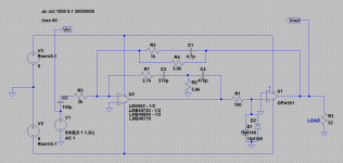
Here is a small example how you can approach this design.
I like it! I like it enough to build it, in fact. I may have just that much circuit fabbed to play around with. Thanks again for your input!
Attachments
Last edited:
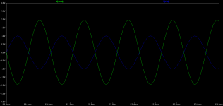
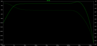
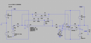
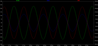
... and a version of sergey888's OPA551 circuit with dual parallel OPA551's running on seperate higher-voltage supplies from a dual tap voltage quadrupler. The second OPA551 is required to handle the output current with the higher voltage output swing. 24Vpeak output swing (17Vrms) into 32R, which is 180mA peak current per OPA551 (the red plot).
Attachments
Last edited:
Sorry, misspelled you nickname ")
Ok, so
Each opamp has individual input offset voltage and individual gain, even if they are the same model. Because of this voltage difference between OP551s outputs is unpredictable and changes with the temperature.
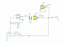
The best you can do is to make it similar to what you using earlier, see the first example.
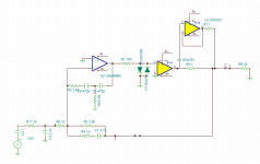
The second example shows also input filter, which you don't want to forget to include into schematic. Output filter is not shown, but also "must have".
I also would like to mentioned that having separate supply rails for the input opamp is a good thing, but may be somewhat redundant. You can easily make lower and filtered voltage right on the palce using RC, R-zener or R-zener-R-C chains. It may allow you to simplify board layout. In fact there is a high chance that distortion performance will be can be compromised by layout, so this is something worth of paying attention.
Ok, so
Each opamp has individual input offset voltage and individual gain, even if they are the same model. Because of this voltage difference between OP551s outputs is unpredictable and changes with the temperature.
The best you can do is to make it similar to what you using earlier, see the first example.
The second example shows also input filter, which you don't want to forget to include into schematic. Output filter is not shown, but also "must have".
I also would like to mentioned that having separate supply rails for the input opamp is a good thing, but may be somewhat redundant. You can easily make lower and filtered voltage right on the palce using RC, R-zener or R-zener-R-C chains. It may allow you to simplify board layout. In fact there is a high chance that distortion performance will be can be compromised by layout, so this is something worth of paying attention.
Attachments
Last edited:
Sergey888 - thanks for the input! Good points.
Thinking it through a bit more I've decided that allowing switchable +/-15Vdc / +/-30Vdc output rails to cover a wide variety of headphones would be a bad idea from a user standpoint. Sooner or later someone would put it in the +/-30Vdc position hooked to their sensitive IEMs, with the volume and/or gain turned up, and **poof** there goes the IEMs like a popcorn kernel.
A higher output voltage amp (+/-30Vdc rails) is probably best built as a specific-purpose DIY amp for those that really need it, ie high impedance 600R cans with lower sensitivity. The same is probably true for any headphone amp with that much voltage swing, like AMB's b22 if used with +/-15Vdc rails. They are best built and used specifically for high impedance phones.
And if that is the case (the amp only powering 600R cans) then the current capability of one OPA551 would be more than enough.
There are so few headphones out there with such a high voltage requirement that I'm not going to have any interest in making a high(er)-voltage-only headphone amp. The world already has AMB's b22 and that Violectric amp using the OPA551 for such things.
Back to fiddling around with the current version. I'll read up on that last group of op amps you posted.
Last edited:
Hi, I have a couple of questions.
Should I install R32 for the second part of the power supply. It's not on the list but
looks like it needs to be there.
What resolution do you shoot pictures in I got my panels back in black from Proto and
they look great I want to post a picture.
Thanks Tony
Should I install R32 for the second part of the power supply. It's not on the list but
looks like it needs to be there.
What resolution do you shoot pictures in I got my panels back in black from Proto and
they look great I want to post a picture.
Thanks Tony
Tony72: R32 is the 28th resistor down on the list in the resistor section of the BOM, a 3.32K, and it does need to be installed. In the PDF BOM the resistor list continues onto the second page. I have the BOM in excel format now too at the Google link.
Proto Panel does do a good job! I just received another panel from them yesterday. I shoot the photos in 640 x 480.
Proto Panel does do a good job! I just received another panel from them yesterday. I shoot the photos in 640 x 480.

New thread started here,
http://www.diyaudio.com/forums/headphone-systems/244473-o2-headamp-output-booster-pcb.html
Hi I have a couple questions so I can keep going on this.
Does it matter which way IC1 and 2 go as there is no marking on the board?
IC5 has a white stripe does that go where the white circle is?
Where does R74 go I cant find it?
There are 13 decoupling caps and 10 bypass caps. Do some not get them?
Thanks Tony
Does it matter which way IC1 and 2 go as there is no marking on the board?
IC5 has a white stripe does that go where the white circle is?
Where does R74 go I cant find it?
There are 13 decoupling caps and 10 bypass caps. Do some not get them?
Thanks Tony
Tony - more good finds! Thank you for letting me know. It is easy to miss things like this when designing it all and writing it up.
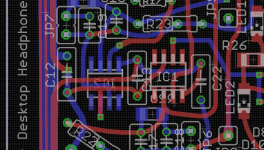
I didn't notice this one because I went by the Eagle layout as much as the board labelling when I stuffed mine. Turns out the Eagle part library I used has a marking problem here. I've attached an image below of what shows up on the board layout in Eagle. Those double bands on the side of IC1 and IC2 correspond to the bevelled edge on each. BUT, the marking doesn't show up on the board! I missed that. I just took a look at the part library and Eagle has those markings on the "doc" layer that doesn't print to the board, even though it looks like it does on the layout. I'll fix that.
So... go by that diagram below. Pin 1 on IC1 is at the top of that bevelled edge, so the end next to C13 and the corner towards the bottom of the PCB. For IC2 on the back, pin 1 is the end next to C12 and the corner towards the top of the PCB.
That is correct, that upper left corner of the chip, towards the top of the board. There is a label problem here though. I just noticed the "IC5" label wound up on the bottom of the board. In Eagle that wound up on the bottom silk screen somehow. I'll fix that one too.
If anyone spots any more labels on the wrong side of the board like this, please do let me know.
R74 isn't on your version of the board. That is one thing I added on the latest version. It makes an insignificant difference in one of the rail voltages, like 7.01Vdc instead of 6.97Vdc. Won't affect operation at all. I wanted to move R31 up a little on the board which left some space. I couldn't resist adding the small tweak.
You are probably comparing the 13 0.22uF 50V film "decoupling" caps and those 10 0.001uF 50V axial ceramic caps labelled "optional" on the BOM with no part numbers. I should definitely add more explanation here in the build instructions for those "optional" ceramic caps.
All 13 of those 0.22uF caps are used, but you can leave all 10 of those axial caps off. There seems to be a running debate out there whether film caps used for decoupling should also be paralleled with a small COG/NPO ceramic to take care of any potential higher frequency oscillation. Those 10 axial caps would be soldered on underneath the PCB, right across the leads of 10 of those 0.22uF caps (to keep lead length to an absolute minimum). BUT, during testing I saw no oscillation at all up to the 80mHz or so bandwith of the scope+probe, so those caps really are not needed. But in case someone just really insists on bypassing their film caps I wanted to include a part number that would do the job.
Does it matter which way IC1 and 2 go as there is no marking on the board?
I didn't notice this one because I went by the Eagle layout as much as the board labelling when I stuffed mine. Turns out the Eagle part library I used has a marking problem here. I've attached an image below of what shows up on the board layout in Eagle. Those double bands on the side of IC1 and IC2 correspond to the bevelled edge on each. BUT, the marking doesn't show up on the board! I missed that. I just took a look at the part library and Eagle has those markings on the "doc" layer that doesn't print to the board, even though it looks like it does on the layout. I'll fix that.
So... go by that diagram below. Pin 1 on IC1 is at the top of that bevelled edge, so the end next to C13 and the corner towards the bottom of the PCB. For IC2 on the back, pin 1 is the end next to C12 and the corner towards the top of the PCB.
IC5 has a white stripe does that go where the white circle is?
That is correct, that upper left corner of the chip, towards the top of the board. There is a label problem here though. I just noticed the "IC5" label wound up on the bottom of the board. In Eagle that wound up on the bottom silk screen somehow. I'll fix that one too.
If anyone spots any more labels on the wrong side of the board like this, please do let me know.
Where does R74 go I cant find it?
R74 isn't on your version of the board. That is one thing I added on the latest version. It makes an insignificant difference in one of the rail voltages, like 7.01Vdc instead of 6.97Vdc.
Won't affect operation at all. I wanted to move R31 up a little on the board which left some space. I couldn't resist adding the small tweak.There are 13 decoupling caps and 10 bypass caps. Do some not get them?
You are probably comparing the 13 0.22uF 50V film "decoupling" caps and those 10 0.001uF 50V axial ceramic caps labelled "optional" on the BOM with no part numbers. I should definitely add more explanation here in the build instructions for those "optional" ceramic caps.
All 13 of those 0.22uF caps are used, but you can leave all 10 of those axial caps off. There seems to be a running debate out there whether film caps used for decoupling should also be paralleled with a small COG/NPO ceramic to take care of any potential higher frequency oscillation. Those 10 axial caps would be soldered on underneath the PCB, right across the leads of 10 of those 0.22uF caps (to keep lead length to an absolute minimum). BUT, during testing I saw no oscillation at all up to the 80mHz or so bandwith of the scope+probe, so those caps really are not needed. But in case someone just really insists on bypassing their film caps I wanted to include a part number that would do the job.
Attachments
Hey Tony,
Those 1/8 watt resistors are the best way to go. 1/8 watt is all that is needed there and the 1/8 watters are the smallest and easiest to work with. In fact, the maximum dissipation in those resistors would be around sqr(360mA [rms]) * (0.5R) = 0.065 = 1/16 watt.
The problem came in that Mouser doesn't stock low-ohm resistors in 1/8 watt, just 1/4 watt and higher, so that is what I put in the BOM. Those 1/4 watt size have to be mounted standing on end to fit whereas the 1/8 watt can lie flat. The Mouser resistors are actually rated at 1 watt dissipation but are just 1/4 watt physical size. How about that for a mess?
Since writing up the BOM I found a vendor on eBay selling 0.5R 1/8 watt in 100 piece lots for $4 or so and stocked up. If anyone building the amp needs the 0.5R 1/8 watt resistors just post in the vendor thread for this project or send me a PM. They are yours for $0.50 plus postage. Or go out to eBay and search for "1/8 watt 0.5 ohm" and you will come up with that same (Hong Kong, took 4 weeks to arrive) vendor.
Last edited:
Hi, Finished the amp this afternoon ran all the tests then hooked all the cheep stuff. Played from the getgo. Left and right volume and gain all was good. After about 5 min C51 popped. I tested the voltages again and got JP12 -6.95 & -15.92. JP13 7 & 16.05. I also have C52 left over I cant find it on the board. I have looked the board over and I dont see anything? What do you think.
Thanks Tony
Thanks Tony
Hi, Finished the amp this afternoon ran all the tests then hooked all the cheep stuff. Played from the getgo.
Hey first off, congratulations on your build!! Quite a bit more work goes into this build than the O2, with all the surface mount parts and about 3 times as many parts. That is just terrific yours worked the first time. You did a very careful and thorough build to have it work the first time like that.
The good news is that your problem is an easy fix.
I'll bet you didn't see post #152 in this thread. I had exactly the same thing happen and made a BOM change. You probably used the 22uF 20V organic polymer capacitor that I originally specified. I changed C50 and C51 to 100uF 25V low ESR electrolytics (Mouser #647-UPM1E101MED at $0.39 each) in the latest BOM at the Google Drive link:https://drive.google.com/folderview?id=0B67cJELZW-i8VmhVNk5PODNtZnc&usp=sharing (80 x 160 -> 8_11_2013)
The even better news is that you can probably get Mouser to send you the new parts at no change. There is absolutely no reason for that orginal organic polymer electrolytic capacitor I specified to be going up in smoke like that. It is well within its voltage rating on that 16V power supply rail. The capacitor is simply defective. Those organic polymers are apparently a fairly new technology.
When my C51 went up in smoke I emailed Mouser customer service with the problem and asked that they refund those capacitors back. They did, no problem! Mouser is good about that. They have sent replacement parts at no charge for a couple of bad parts I've received over the years. So in your case I would suggest asking them to send you two of the new capacitors (647-UPM1E101MED) as replacements, certainly not another one of those defective organic polys. Please feel free to point them to this post if it will help. Make sure you replace C50 too, even if it hasn't smoked yet.
Some more good news is that it isn't likely the defective cap damaged anything on the board. I specifically oversized the power supply traces to handle shorted parts without fusing since the voltage regulators have current limiting. The traces can handle the overcurrent for a few fractions of a second until the current limiting kicks in.
If Mouser gives you any static please PM me and I'll put a couple in an envelope and send them to you no charge.
Last edited:
C51 polarity is reversed on the PC board!
Tony - Well..... turns out C51 going up in smoke is my fault after all. I got to thinking about it some more, that only C51 is burning up and not C50 on either your board or mine, and figured I better double-check the polarity on the schematic. Sure enough I have the polarity of C51 reversed. I drew that one a different way on the schematic than the other caps and biffed it. Lol - I'll take back all those those comments about Mouser's organic polymer. At least this solves the mystery of why the 20V cap was going up in smoke on 16v rails.
The replacement C51 electrolytic on the boards I've built must all be in backwards too. Apparently the regular aluminum electrolytics are just better at withstanding reverse polarity abuse. I'll have to flip my C51's too. Actually best to replace them entirely after being exposed to reverse polarity, if anyone else building this amp has run into this yet. C50 and C51 are in there for oscillation prevention (bypass and decoupling) for the preamp chip.
I'll send you a replacement. At this point lets stay with the original organic polymer. I'll send one of those so it matches your existing C50. No need to replace your C50, I have the polarity on that one correct.
I also forgot to say you don't have to solder in that C52. That is one of the EMI suppression caps and it is entirely optional.
Tony - Well..... turns out C51 going up in smoke is my fault after all.
I got to thinking about it some more, that only C51 is burning up and not C50 on either your board or mine, and figured I better double-check the polarity on the schematic. Sure enough I have the polarity of C51 reversed. I drew that one a different way on the schematic than the other caps and biffed it. Lol - I'll take back all those those comments about Mouser's organic polymer. At least this solves the mystery of why the 20V cap was going up in smoke on 16v rails. The replacement C51 electrolytic on the boards I've built must all be in backwards too. Apparently the regular aluminum electrolytics are just better at withstanding reverse polarity abuse. I'll have to flip my C51's too.
Actually best to replace them entirely after being exposed to reverse polarity, if anyone else building this amp has run into this yet. C50 and C51 are in there for oscillation prevention (bypass and decoupling) for the preamp chip. I'll send you a replacement. At this point lets stay with the original organic polymer. I'll send one of those so it matches your existing C50. No need to replace your C50, I have the polarity on that one correct.
I also forgot to say you don't have to solder in that C52. That is one of the EMI suppression caps and it is entirely optional.
Last edited:
Tony - more follow-up. I was looking at the wrong BOM version last night on C52. You don't have one and I should remove that from the BOM. C52 was a capacitor that was used in a version of the board that had a separate voltage regulator for the output relay.
I also just realized that you may already be using those updated-BOM 100uF C51's and that smoked. I probably just got lucky that none of mine have toasted yet with the new caps, being installed in reverse. Those are fine too. I'll send you one of each, a 22uF organic polymer and a 100uF low esr aluminum electro and just use whichever one matches your C50.
I have been expecting that the first question I would get from anyone building this amp is why no sound comes out when they first turn it on after the build. It is easy to forget about that time-delay relay on the headphones output. That tripped me up too a couple of times during the testing. When I've made an electrical change and then an amp is first powered up, no immediate sound output usually means something is wrong and I instinctively dive for the on/off switch.
I also just realized that you may already be using those updated-BOM 100uF C51's and that smoked. I probably just got lucky that none of mine have toasted yet with the new caps, being installed in reverse.
Those are fine too. I'll send you one of each, a 22uF organic polymer and a 100uF low esr aluminum electro and just use whichever one matches your C50.I have been expecting that the first question I would get from anyone building this amp is why no sound comes out when they first turn it on after the build. It is easy to forget about that time-delay relay on the headphones output. That tripped me up too a couple of times during the testing. When I've made an electrical change and then an amp is first powered up, no immediate sound output usually means something is wrong and I instinctively dive for the on/off switch.
Last edited:
agdr or maybe someone else. Did someone get this to work or is it to be considered a dead end? If buildable as is how does it sound? How is it compared to the O2 + booster?
Turbon - the ODA is still alive and kicking!
So far Tony is the only one of the builders who has let me know that his is finished and working, after replacing the cap in the post above. It sounds like he is getting that same ultra-quiet background I had on my builds with his headphones. I've been meaning to post that if any of the other folks building this project are stuck in any way, please post or PM if I can help.
Here are some of the differences between this ODA project and the O2 booster board:
* Portability. The O2 booster board is still battery friendly, consuming only sliightly more idle current than the NJM4556A's it replaces. The ODA is not portable at all - no batteries and larger case. The ODA uses considerably more idle current than the O2 + booster board.
* Noise, or lack of it. The ODA here should be pretty much dead silent in terms of background noise, due to the lower noise power supply, lower noise gain chips (LME49990), 1k pot and associated 4.99K ground return resistor (lower Johnson noise) taking full advantage of the 600R drive capability of the LME49990. The NJM2068 is only rated to 2K drive ability, hence the noiser 10K pot and 40.2K resistor in the O2. And finally the higher S/N of the increased number of paralleled NJM4556As.
* Output current. The ODA is good for full sine wave testing at 320mA per channel due to the heatsinked voltage regulators and multiple output chips. The O2 + booster can only burst up past 200mA/channel, in a "music power" 3x peak over average sense, due to the O2's voltage regulators not being heatsinked.
* More gain settings. The ODA has a 4 position switch vs. the 2 position slider in the O2.
* DC output offset voltage. Extremely low DC output offset voltage with the O2 + booster board, around 20uV. The ODA still should result in smaller DC offset than the O2 alone, but nowhere near as low as 20uV. This may change in the ODA board revision I'm doing right now. I'm adding the manual DC offset null circuit I posted in this thread. It should be possible to drop the DC offset to around 200uV or so. As I discovered earlier in this thread is just isn't possible to loop anything with lower DC offset (another op amp) around the NJM4556A's due to their low bandwidth and slew rate. By comparison the BW and slew of the LME49600 in the O2 booster board is significantly faster than the OPA140.
* Better jacks. The ODA uses vertical Swichcraft 1/8" jacks vs. the CUI things in the O2. Neutrik 1/4" output jack on the ODA.
* RCA input. Standard with the ODA, can be added externally to the O2 if the taller case is used.
* Optional bass boost on the ODA. Just populate the 2 resistors and caps on the PC board. None with the O2, although I did publish that modification in the O2 mod thread.
* Clipping detect circuit and LED with the ODA. None with the O2 + booster.
* Pre-amp and pre-amp RCA out on the ODA, none with the O2+booster.
* Power plug and on/off switch in the back with the ODA. Still in front with the ODA+booster.
* Two power supply voltage levels, switchable, with the ODA. Just the one with the O2+booster, although the booster board now does allow the O2 to be modified for +/-15Vdc and +/-18Vdc.
* Power supply LEDs on each rail with the ODA. Added to the O2 by the booster board!
* 1/4" output jack. Standard on the ODA. Can be added externally with the O2 if a larger case is used.
* Output 6-second time delay relay to let the circuitry stabilize before connecting the headphones on the ODA for no turn-on thump. Accelerated relay opening on shutoff by looping the coil through on/off switch contacts for no turn-off thump. The O2+booster board is still limited to NwAvGuy's power management circuit, although the booster boards adds latching upon low battery to keep the circuit from oscillating. The booster also adds two resistors to help lessen any turn-off thump with the O2.
* Option of using 2 boards and putting the power supply section completely on the back board, along with space for an ODAC, with the ODA. No such option with the O2, although with a bunch of DIY cut and jumper it may be possible.
I really should finsh up the few changes I've been wanting to make to this PCB and documentation and have another batch of boards run and tested before getting sidetracked on things like the paralleled LME49990 amp.
I've been promissing that for awhile. I'll get that done.As for how the ODA sounds, subjectively, vs. the O2 + booster board, I'll leave others to comment on that. I'm just the engineer.
Last edited:
- Home
- Amplifiers
- Headphone Systems
- A version of an O2 Desktop Amp (ODA)