In this particular circuit, each 12AX7 half, biased at 1.1mA, dynamically swings under 5uA peak-peak worst case (at full amplitude output at 20kHz,
Correction - That's 5uA peak. Distortion for the entire front-end running closed loop (as tested) is in the order of .001 - 0.002% or so at 20kHz.
Last edited:
I've pretty much have this design fully tested now. I'm currently assembling the chassis.
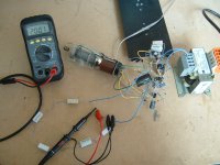
Here is the final circuit of the 200V regulator module, which I've decided to layout a PCB for. As stated previously, two of these modules will be used for each channel, connected in series to provide +/-200V.
Also pictured is the fully functional prototype, built rats nest style. The string of ceramic wirewound resistors were for load testing.
At rated load the output ripple measured exaclty as simmed, at ~800uV rms, which is more than low enough for this application (and will be further reduced by the extra C and RC filtering on each front-end PCB).
Attachments

- Status
- This old topic is closed. If you want to reopen this topic, contact a moderator using the "Report Post" button.
- Home
- Amplifiers
- Solid State
- A tubular 'Blameless'