Well it's nearly11pm and visitors left just 30 minutes ago. Didn't get much done today and I currently have a headache.
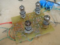
Anyway, here is the (not really all that exciting) triode heater supply PCB - 4 individual 12.6V regulated supplies.
A project like this (mixing tubes with SS discrete power and small-signal IC) soon gets a little mental in the power supply department, due to all the voltage rails required and the heater requirements.
Each channel has two pairs of twin triodes. The heaters of one pair are referenced to ground while the heaters of the other pair are referenced to the -200V rail (so as not to exceed Vk-h voltage limits).
And of course, the stereo channels require heater supplies independent of each other to prevent the generation of additional ground loops.
There is another circuit board containing a pair of 3.5VA PCB mount transformers and misc components to make a pair of independent +/-12V regulated supplies to power the differential input circuitry of each channel.
Then there is the control/protection PCB which contains a 10VA PCB mount transformer along with the +12 unregulated supply for the speaker and HT relays and the +5V regulator for the uC.
Then there is the two twin-secondary heater transformers for the 807's along with the two twin-secondary isolation transformers that provide for the two independent +/-200V regulated supplies.
That covers all the PSU stuff except for the big toroid powering the class B output stages.
I'll post the details of most of this up tomorrow, if nothing else get in the way......
Attachments

Last edited:
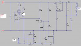
The 200V regulator module. Individual transformer secondaries are used for each module and a pair are connected in series to provide +/-200V.
Output ripple is very low and the regulator is stable into any load capacitance.
The circuitry is pretty simple and I haven't decided at this point if I'll do a PCB or just wire the components point-point on tagstrips mounted beneath the chassis by the 807 valve sockets.
Output ripple is very low and the regulator is stable into any load capacitance.
The circuitry is pretty simple and I haven't decided at this point if I'll do a PCB or just wire the components point-point on tagstrips mounted beneath the chassis by the 807 valve sockets.
Attachments
Last edited:
its nice to see a hybrid done the obvious way ...
years ago when I used to be a service tech at a few high end stores there were a few commercial hybrids that had sand front ends and glass outputs ... always seemed bass ackwards ...
and yes I know sand and glass are both the same thing - of course transistors aren't really sand but almost pure Si, but I digress
Last edited:
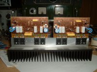
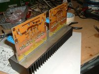
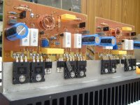
Well that's the output stages loaded. Now they just need to be wired up. Nothing out of the ordinary here; just a plain double EF. The two TO-126 transistors on each board (and associated components) form a voltage clamp for the VAS, which prevents the pre-driver transistor bases from being driven beyond the rail voltages for the output stage. This is required because the tubular VAS runs on +/-200V rails, of course.
The PCB's are sprayed with clear, solder-through conformabe coating - I like the copper look. The reason the big electo's are a little proud of the PCB is because that's the only way (with them bent over) to get a soldering iron tip underneath to solder one of the legs to the ground plane. No PTH's here, unfortunately.
I'll be starting the front-end (input/VAS) PCB tomorrow. I'll post up some more schematics in the meantime, as I get time to generate the *.jpg's.
Attachments
Last edited:
Ugh.. late night brain fade....
I guess you're talking about the INA217 in-amp differential input circuitry. Nope, have not breadboarded that either, but it’s pretty straightforward. Used these series (INAXXX) of in-amps a million times in other things. Don’t foresee any issues here in an audio application; should work fine.
I guess you're talking about the INA217 in-amp differential input circuitry. Nope, have not breadboarded that either, but it’s pretty straightforward. Used these series (INAXXX) of in-amps a million times in other things. Don’t foresee any issues here in an audio application; should work fine.
Ugh.. late night brain fade....
I guess you're talking about the INA217 in-amp differential input circuitry.
No brain fade, I really was talking about the tube opamp portion. I haven't done it myself, but a friend of mine who has found much higher distortion than he had expected. Intuitively, the load line for the 12AX7 is nearly vertical, which is a high distortion loading. But experiment trumps intuition...
Can't comment without seeing his circuit, but here the 12AX7 is lightly loaded and the distortion is pretty low (though not as low as when using emitter-degenerated transistors).
In this particular circuit, each 12AX7 half, biased at 1.1mA, dynamically swings under 5uA peak-peak worst case (at full amplitude output at 20kHz, when the loading by the 15pF C'dom is greatest). Also, even order distortion is cancelled by the LTP current mirror.
The 12AX7 has low gm compared to a bipolar input stage, so with a moderate closed loop gain, such a small Cdom is all that is required.
One great way to pooch-screw a hybrid op-amp using a 12AX7 as the input LTP would be to use resistive plate loading, for example.
...If any of that makes sense
Last edited:
They're tools, not toys......
Some of my most fun toys are my tools!
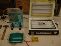
And your picture of the bubble etch gave me an idea for making one of my own.
What is it you've got in the tank in that picture? The developer looks to be in the glass tray at the front. The ferric chloride I use to etch certainly isn't the colour in the tank.
I guess the needle nose are being used as tweezers.
And the hammer's for when it goes wrong, and you need something to hit something with.
Ferric chloride is awful stuff. The etchant is amonium persulphate. It comes as a powder that you dissolve in warm water. It works best at about 60degC - thats what the heater is for. The hammer handle just stops the fish tank air pump from walking about the floor
Currently I use a water bath to keep my etchant warm and I really loathe standing there agitating the PCBs myself, as they just sit in a tray. I wouldn't mind so much but 2oz boards take a while to etch, especially when the solution is losing its strength. Usually I just give up and make some more up to get the job over and done with.
Originally I purchased 2.5kgs of etchant and I've almost used it all up, I might give amonium persulphate a go for the next lot I buy.
Ta for the info.
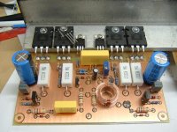
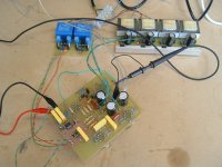
Progress on this project has been slow because some critical parts that I still need are on back-order, but today I got a complete front-end circuit board up and running and tested – it worked first go.
The final schematic is attached. I made a few alterations, which include biasing changes to the cathode follower current source.
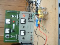
In the photos 3 boards can be seen. The large one with the 4 transformers is the one containing the four independent 12.6V regulators for the triode filaments. The smaller board with the two blue transformers is the one containing the two independent +/-12V regulators for the balanced input circuitry of each channel.
I have not built up the HV tube regulators yet, and for testing purposed the +/-200V rails were provided by the two HV power supplies (series connected) that can be seen in the photo.
Since the VAS has a cathode follower buffer, the complete front-end can be tested without the power output stage, as the cathode follower can easily drive feedback resistors (R12 and R13), and this is how I tested it.
J15 and J17 (which will connect to either side of the Vbe multiplier for the power output stage) were just shorted together and connected directly to the nfb input, J5. I ran the test with the servo IC unplugged. It seems my 12AX7 is well matched as I only had about a 20mV offset voltage at the output
The scope shot shows a 60Vpeak-peak 10kHz squarewave output. 2-pole compensation is used here and the slewrate is about 130V/us. However the slewrate is reduced and overshoot inherent with 2-pole compensation is killed by the RC filter R10/C4.
The final schematic is attached. I made a few alterations, which include biasing changes to the cathode follower current source.
In the photos 3 boards can be seen. The large one with the 4 transformers is the one containing the four independent 12.6V regulators for the triode filaments. The smaller board with the two blue transformers is the one containing the two independent +/-12V regulators for the balanced input circuitry of each channel.
I have not built up the HV tube regulators yet, and for testing purposed the +/-200V rails were provided by the two HV power supplies (series connected) that can be seen in the photo.
Since the VAS has a cathode follower buffer, the complete front-end can be tested without the power output stage, as the cathode follower can easily drive feedback resistors (R12 and R13), and this is how I tested it.
J15 and J17 (which will connect to either side of the Vbe multiplier for the power output stage) were just shorted together and connected directly to the nfb input, J5. I ran the test with the servo IC unplugged. It seems my 12AX7 is well matched as I only had about a 20mV offset voltage at the output
The scope shot shows a 60Vpeak-peak 10kHz squarewave output. 2-pole compensation is used here and the slewrate is about 130V/us. However the slewrate is reduced and overshoot inherent with 2-pole compensation is killed by the RC filter R10/C4.
Attachments

Last edited:
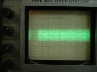
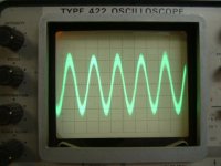
Here are a few pics to show the efficacy of balanced inputs at rejecting noise and RF. I connected my audio signal generator to the input of the front-end circuit board with a pair of long, unshielded leads which I draped over my workbench.
I live near a high power AM broadcast transmitter. What you see in the first scope shot is an ABC Radio National broadcast at 600 and something kHz, as picked up by the above mentioned leads and probed at one of the input pins of the INA217. This RF is picked up by both the ‘hot’ lead and the ground lead, and is applied to the INA217 differential inputs as a common mode signal.
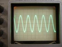
For the second scope shot I turned up the amplitude control on the signal generator and here you can see the RF superimposed onto a 1kHz sinewave.
The last photo shows the 1kHz sinewave signal at the output (pin 6) of the INA217.
I live near a high power AM broadcast transmitter. What you see in the first scope shot is an ABC Radio National broadcast at 600 and something kHz, as picked up by the above mentioned leads and probed at one of the input pins of the INA217. This RF is picked up by both the ‘hot’ lead and the ground lead, and is applied to the INA217 differential inputs as a common mode signal.
For the second scope shot I turned up the amplitude control on the signal generator and here you can see the RF superimposed onto a 1kHz sinewave.
The last photo shows the 1kHz sinewave signal at the output (pin 6) of the INA217.
Attachments
- Status
- This old topic is closed. If you want to reopen this topic, contact a moderator using the "Report Post" button.
- Home
- Amplifiers
- Solid State
- A tubular 'Blameless'