Thanks.4.
I recommend to use TX2575 from Texas Components as I/V Resistors, i assemble mine recently, they are game changer in stage and resolution of sound.
btw.. i use Panasonic FC or FR (better) in Supply Application's with always good results.
I have seen the contact here:
http://www.diyaudio.com/forums/blogs/dvb-projekt/723-best-source-tx2575-naked-z-foil-resistor.html
Request sent
")
Something to consider
I wonder, though I do have TX2575s for this position, if there might be something gained with a higher power resistor?
If Doede would give an opinion here? I remember someone saying they were pleased when using the 2W tantalums - I have no idea how much power runs through the resistor though I would think with four boards it might be considerable. I think of AUDIO RESEARCH using much larger than needed power rating in their boxes.
It might be we should parallel TX2575s in this position? I know that would be expensive but could they be stressed in this position? Hoping for the opinion of someone who knows!
Thanks.
I have seen the contact here:
http://www.diyaudio.com/forums/blogs/dvb-projekt/723-best-source-tx2575-naked-z-foil-resistor.html
Request sent
I wonder, though I do have TX2575s for this position, if there might be something gained with a higher power resistor?
If Doede would give an opinion here? I remember someone saying they were pleased when using the 2W tantalums - I have no idea how much power runs through the resistor though I would think with four boards it might be considerable. I think of AUDIO RESEARCH using much larger than needed power rating in their boxes.
It might be we should parallel TX2575s in this position? I know that would be expensive but could they be stressed in this position? Hoping for the opinion of someone who knows!
I have no idea how much power runs through the resistor though I would think with four boards it might be considerable.
DDDAC said:Ohms law will do also here
DC Output is 2,7 Volt, so power dissipation is 2,7 * 2,7 / Ri/v
or 7,3 / R
example:
1 deck 7,3 / 134 = 55mW
8 deck 7,3 / 17 = 430mW
if you use Ra AND Rb Position, values go by half of course...
rule of thumb, use for power Rating double the disipation
The answer is there http://www.diyaudio.com/forums/digital-line-level/224108-nos-192-24-dac-pcm1794-waveio-usb-input-142.html#post3871090
Supersurfer and other chose 2W because overkill lowers the thermal noise.
Supersurfer and other chose 2W because overkill lowers the thermal noise.
The answer is there http://www.diyaudio.com/forums/digital-line-level/224108-nos-192-24-dac-pcm1794-waveio-usb-input-142.html#post3871090
Supersurfer and other chose 2W because overkill lowers the thermal noise.
Correct,
It's thermal stability that plays a role here (a small role though
)Also, if the choke feeds a CCS, the current through the trannie stays constant, makes the type if diode much less relevant.
With Supersurfers shunts, this will effectively be a CCS as they shunt what they don't supply to the load. Perhaps this is part of why the choke loading sounds good.
Chuz,
Drew.
Yep! There is a nice constant current through the power supply, this is what a choke likes most.
I do not think it has any positive effect on the diode selection; every AC cycle when the diode starts conducting the inrush current will be high. This high inrush current loads your transformer core and can (in some case will) make it saturate, even for a fraction of a second.
Different diode types have different switch-on characteristics; the worst type create a very high current peak that saturates the transformer core.
Shottky type diodes are known to have a much more smooth characteristic.
Regards,


Nice!
What board do you use at the output?
Thanks.
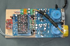
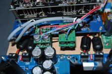
That are four diamond buffers from Per-Anders (Forum Member), more details see here.
Regards
Attachments
Last edited:
Thanks.
That are four diamond buffers from Per-Anders (Forum Member), more details see here.
Regards
Intresting build, some novel idea's here. Why are using all the line filters? Have you tried with and without the output buffers, how was the difference?
Intresting build, some novel idea's here. Why are using all the line filters? Have you tried with and without the output buffers, how was the difference?
The line filters are to reduce high frequency. I also recommend to use a power line filter for i.e. Schaffner FN2090 and a EMI Power Cable i.e. Eupen GNML (with ferrit poweder around each wire and good shild) this helps to detach music from speaker, open sound stage.
With Buffer the sound stage increase, in addition i want to be unattached from the load, the DAC should 'always sound equal' to different load conditions, so this is out of my mind while play with different system setups
Capacitors to replace stock nichicons
I'm thinking of replacing some or all of the nichicon caps on the dac board. The referenced caps below apply to the left channel. Any comments on doing this?
1) Use an oscon in the digital power pin (vdd: C27)?
2) Use silmic II's for the chip's analog pins (vcc: C17,C21,C22,C32)?
3) Use panasonic FR's for the rest of the caps?
4) Use an oscon on motherboard's C3 since it's feeding digital chips and vdd-out?
Or replacing all these caps results in sound improvements so small it's not worth the work of exchanging them?
Also, I see a lot of mods to the power supply boards, using large trafos. Would it make more sense to use separate smaller trafos to feed the left and right side of the dac board, since the groundplanes are separated? I think carlsor is feeding 8v straight to the dac board in his dac, I would do the same but using two separate trafos/pre-regs? I would not use large trafos but ones similar to the stock one on Doede's power supply, but keeping the trafos separate would minimize interactions between the two channel's demands on the single trafo?
I don't know enough about these things so any comments/corrections would be most welcome!
Thanks in advance.
For some reasons, I get mails from People thinking I closed my Website Ofcourse that is not right. I only stopped selling kits by MYSELF.... There is a link on the sales page to any one who still want to aquire kits and so. It os now done by someone who does this for a living
check my site please !
Ofcourse that is not right. I only stopped selling kits by MYSELF.... There is a link on the sales page to any one who still want to aquire kits and so. It os now done by someone who does this for a living check my site please !
The line filters are to reduce high frequency. I also recommend to use a power line filter for i.e. Schaffner FN2090 and a EMI Power Cable i.e. Eupen GNML (with ferrit poweder around each wire and good shild) this helps to detach music from speaker, open sound stage.
With Buffer the sound stage increase, in addition i want to be unattached from the load, the DAC should 'always sound equal' to different load conditions, so this is out of my mind while play with different system setups
I used EMI filters in some builds, but was advised against them for the risk of smothering the PSU, which makes sense to me. Same goes for the line filters, there are mixed opinions about these. It also all depends on how clean your AC is and how much interference you have. Needless to say removing sources of interference close to the equipment or in the house is a good place to start as well.
I used EMI filters in some builds, but was advised against them for the risk of smothering the PSU, which makes sense to me. Same goes for the line filters, there are mixed opinions about these. It also all depends on how clean your AC is and how much interference you have. Needless to say removing sources of interference close to the equipment or in the house is a good place to start as well.
I complete agree !
On other Hand the Primary Current of a DAC or Preamp is very low (Let's say 23 Watt ~ 100mA at 230V line volatge).In addition there are a lot of filter and sotrage capacitors which need to make DC voltage, at least my consideration was that i don't expect that a EMI Filter smothering in this kind of application... an power amp is different story.
Regards
Recently I've discussed with Brian Lowe @ Belleson about putting his regs on DDDAC.
I showed him the left channel of the DAC board (Doede's silkscreen), and he advised this (he is OK for publishing his reply) :
"For the circuit you show, I suggest remove R1, R2, and L2, they slow the delivery of current to the load. Maybe remove L1 also, or evaluate with and without. 10uH is small and may be good to block high frequency noise without limiting current to the regulator and load. We have a customer who uses an inductor (10mH) at the input and likes it. C1, C2, C3, C4, C5 are good to keep. I also suggest 100uF in parallel with C14."
"We recommend 100uF capacitor from Superpower output to ground for best dynamic response."
About that 100uF capacitor, he gave no advice on the type : he didn't test them, and the value came from tests with standard Nichicons.
Hope it helps !
Recently I've discussed with Brian Lowe @ Belleson about putting his regs on DDDAC.
I showed him the left channel of the DAC board (Doede's silkscreen), and he advised this (he is OK for publishing his reply) :
"For the circuit you show, I suggest remove R1, R2, and L2, they slow the delivery of current to the load. Maybe remove L1 also, or evaluate with and without. 10uH is small and may be good to block high frequency noise without limiting current to the regulator and load. We have a customer who uses an inductor (10mH) at the input and likes it. C1, C2, C3, C4, C5 are good to keep. I also suggest 100uF in parallel with C14."
"We recommend 100uF capacitor from Superpower output to ground for best dynamic response."
About that 100uF capacitor, he gave no advice on the type : he didn't test them, and the value came from tests with standard Nichicons.
Hope it helps !
Many thanks for sharing this usful information, i also ordered some Belleson Regulators
- Home
- Source & Line
- Digital Line Level
- A NOS 192/24 DAC with the PCM1794 (and WaveIO USB input)