digital and analogue power supplies at turn on
AS I get close to actually having something to power up I started to wonder if the digital supply and the analogue supply must be powered up simultaneously?
One part of me would like to handle the incoming AC for the digital supply in a different way which would require a separate power cord but it is not that big of a deal.
Has anyone tried turning their DAC on one supply at a time or is everyone letting the two supplies share a common power switch?
Have you done what in post #547
I will try it. I don't use digital volume control at all tho. I would be surprised if it is a stressed / faulty resistor but you never know! Thanks for the ideas anyway
David
..Has anyone tried turning their DAC on one supply at a time ..?
Hi Rick, I'm presuming you are using the "digital" supply for a USB board (Wave IO board, or similair) and the "analogue" supply connecting to the DDDAC mainboard. (arguably there is an digital and analogue side to the DDDAC boards as well). If so, my power on sequence is: source (PC or BBB in my case)-> USB (Wave IO board) -> DDDAC (power to the mainboard connector) -> Power amp. No problem doing this
Last edited:
The WaveIO is using Doede's supply. Then there are the two supplies for the digital and analogue sections of the board, so three supplies in total.
Eventually I will leave all of this ON all the time but for the occasions when I must turn it off (and back on).
In more detail - the power for the analogue section, ultimately 8 volts after the regulator will use the power input on the DAC board - I am using the filter on the board (the series resistor and the four caps), after this a short wire to the input of the 8 volts regulator. This regulator uses the board's grounding.
The digital supply (ultimately 3.3 volts) is divorced from the board - leads from its input and ground are added which will be attached to its own power supply. I got a little ahead of myself - the 3.3 supply's ground is attached to the board ground at the edge where the daisy chaining occurs. Wish I could think of a better way to put that, but the power input for the 3.3 is attached, ONLY, to its supply.
So I can power the two sections up separately. Whether that is dangerous for the life of the chip is the question.
I remember Doede warning about about testing the board without it being connected to the mainboard but I would think that if the digital section was powered first there should not be a problem but I have no idea or, rather, all I have is idea - no knowledge.
Last edited:
Hello,
Will call it a day for the dac for the weeks to come.
Did receive my second subwoofer and an anti mode double core yesterday ( havent even connected my normal anti mode in my other set) Still busy modifying a Virtue sensation integrated to be used as a power amp with a big battery power supply.
The 2 different lundahl chokes have been send by my supplier in Belgium. Will do some test to verify if i can obtain the right dc output with the 15 volts ac transformer once the sensation is connected and both subwoofers are working in both of my sets. They are connected wireless so with an extra transmitter i can use them in both sets. Crossover is settled by a cap in both of my sensations so probably will just have to adjust the gain when switching from one set to the other.
Have to get it right before spending money on the dac. Already have the power supply. 4 boards with shunts and the output transformer with gain will be a serious investment. If i am right you need the extra boards with them.
Sincere greetings, edward
Hi Stefan & James,
Wonder if you could please elaborate why only BB were wired on your DAC output? What has happened to AA?
According to James, the closer the tent shunt is to the DAC chip will yield best sonic outcome, however, I can only see it is practicable for 3.3V digital Shunt. Analog 8V Shunt still has to go through others 47uf cap for other two inputs? i.e we could only get it close to only one input but not all without remove all 47uf path post Shunt. Any thoughts?
I am close to pull together my 11-DAC with Shunts. Still await for the tent Shunts' final fabrication and shipped. Hopefully I will get a shipping update from Guido by end of week if not early next week.
Cheers,
Chanh
Attachments
I remember Doede warning about about testing the board without it being connected to the mainboard but I would think that if the digital section was powered first there should not be a problem but I have no idea or, rather, all I have is idea - no knowledge.
Hi Rick, correct, if you power the DAC board without any I2S Signal connected to it, you might smoke the dac Chips
I always Switch everything ON at the same time no problems
I'm getting a crackling noise-much like a noisy LP-out of one channel of my DDDac. It was not there previously. I'm using a 4 Board set up with Audio Note 2watt resistors on the load function.
A friend had exactly the same experience and describes his experience 'First I had the Dales, then I installed the audio notes: crackle in the right channel. I then swapped the right and left channel resistors, but the crackle was still in the right channel. I went back to the Dales: problem solved, complete mystery'
Anyone else had this? Any ideas?
David
mmm strange Thing with the resistors, may be it has to do with parasitic capacitance....
Are you using the "red usb board" or the "blue SPDIF/USB board"?
if you have the red one, are you using 3.3 Volt Regulator or 5 Volt? Experience Shows that with 5 Volt there is less Chance you have crackles... please check and if necesarry Change to 5 Volt for a try
doede
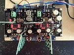
here's a quick few pictures to explain how I've mounted my shunt regs on my dac board. It sounds great and I'm satisfied that this is pretty much as good as the placement can get.
Apologies for the crappy diagrams, I only have my phone with me and very limited Internet access this week, so I've had to make do....
I've mounted the shunts as close to the DAC chip as possible, as per Guido's instructions for best results. In the diagram, light pink is v-in, dark pink is v-out and orange for gnd. I have used the original places for the Wima film caps, as the shunt regs have Wima caps on the output anyway. I wasn't happy that the 8v reg was as close as it could be to all 3 places where the DAC used it, so I cut a couple of tracks and added wire jumpers to make a nice short path for all 3. I've kept the film caps in place for the further 2, but I guess it's questionable as to whether these are needed.
Red on the diagram is where I've cut the tracks and green is where I've added tracks with small wire bridges, but I don't have a picture of that as it's mostly on the underside of the board.
I've removed all the electrolytics around the DAC chip apart from the 2 for the v-com as they work differently and are coupling as apposed to decoupling.
The only way I found (thanks to Stefan for the inspiration) to fit the 8v analog shunt reg in this position was to not use 2 of the output wires (A pos and A neg) that go down to the main board and use that space instead for the shunt board. If you look at the circuit for the main board, these wires are immediately joined anyway, so there's no real difference joining them on the DAC board this way. The newer dac boards have this as an option on the boards, but mine is the older design, so I replicated the same functionality using small wire bridges underneath.
Hopefully this makes sense. let me know if you have any questions, but bare in mind I'm mostly 'off grid' for the next few days.
An externally hosted image should be here but it was not working when we last tested it.
An externally hosted image should be here but it was not working when we last tested it.
An externally hosted image should be here but it was not working when we last tested it.
An externally hosted image should be here but it was not working when we last tested it.
An externally hosted image should be here but it was not working when we last tested it.
An externally hosted image should be here but it was not working when we last tested it.
An externally hosted image should be here but it was not working when we last tested it.
An externally hosted image should be here but it was not working when we last tested it.
An externally hosted image should be here but it was not working when we last tested it.
An externally hosted image should be here but it was not working when we last tested it.
An externally hosted image should be here but it was not working when we last tested it.
An externally hosted image should be here but it was not working when we last tested it.
An externally hosted image should be here but it was not working when we last tested it.
An externally hosted image should be here but it was not working when we last tested it.
An externally hosted image should be here but it was not working when we last tested it.
An externally hosted image should be here but it was not working when we last tested it.
An externally hosted image should be here but it was not working when we last tested it.
Hello,
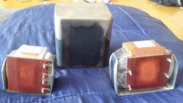
Monday i did receive my set of chokes. One that is been used by some people here and the other one that is a bit bigger.
And gues what i did find some nice 4mm thick iron cans that have been welded for me two decades ago that can be used for potting them. The smallest choke can be fitted in every direction. The biggest one will only fit one way after a minor adjustment inside the can.
The cans have to be sended because they have been in the shed for a long long time.
I will wait for the new boards to appear i think. It is okay to mutulate one board but having 4 boards like this. I think i rather wait a bit longer.
Maybe can start a pre ordering so the first run will be sold 50 %before they are even made.
Sincere greetings, edward
P.s the cans are heavier than the choke it will hide
Attachments
Hi James,
These photos are wonderful! Can't THANK YOU enough!
Obviously the two 47uf are still connecting at 8V path but have no use whatsoever?
I believed my Shunts are shipped yesterday according to Guido, however, I have yet received his tracking confirmation.
I have also ordered Elna Silmic 2 47uf and in total 78 AN tantalum resisters for this mod. They are also on their way from partconnexion.")
These photos are wonderful! Can't THANK YOU enough!
Obviously the two 47uf are still connecting at 8V path but have no use whatsoever?
I believed my Shunts are shipped yesterday according to Guido, however, I have yet received his tracking confirmation.
I have also ordered Elna Silmic 2 47uf and in total 78 AN tantalum resisters for this mod. They are also on their way from partconnexion.
James,
We have arrived at the same conclusion as to how to do this.
One thing I did differently, and I think it has allowed me to save a few millimeters of lead length to the regs is to remove the pins.
These instructions apply to using the BELLESON regulators.
Since I am using the bleeders on the outputs I mount these on the back of the board with their leads, uncut at this point, coming up through the PCB at the bypass cap's position. Also, soldered to this resistor is the output capacitor as required by the BELLESON. Those using the shunts have no need for this, in fact it would be detrimental.
For the 8v I used SILMIC for the 3.3v I used polymer.
Same cuts in the pcb, same wiring from reg output to the electrolytics as yours.
The regs are then threaded through the resistor leads. The DALEs I used have copper leads. Each reg has an added input wire. The 3.3 has an input and a ground. The 8v input can be taken from your favorite place on the board - I connected just past the group of four electrolytics. 3.3v input is not attached to the board at all. 8v ground is left alone, 3.3 ground requires an attached wire which is then attached at the ground point at the edge of the board.
At each reg's input there is a capacitor attached on the reg. Same choices as made before.
I do gain some height with this arrangement. My stand-off are a 25 mm and an 8 mm - much taller but the reg is approx 4 mm from the DAC chip. Who knows if it makes much difference?
The board is not pretty but it is condensed! If I can screw up my courage I will take some photos and post them.
The first channel was a pain but the second was pretty easy. I figure I will modify three more boards in the next month or so.
Now to connect to a power supply. Hoping this will happen tomorrow.
Hi James,
These photos are wonderful! Can't THANK YOU enough!
Obviously the two 47uf are still connecting at 8V path but have no use whatsoever?
I believed my Shunts are shipped yesterday according to Guido, however, I have yet received his tracking confirmation.
I have also ordered Elna Silmic 2 47uf and in total 78 AN tantalum resisters for this mod. They are also on their way from partconnexion.
No problem. I've had so much help and inspiration from here, I'm always happy to return the favour if I can
Those 2 remaining 47uf caps around the DAC are for the vcom pins (whatever they are) and are still used. If you check the schematic, you will see that they are in coupling or dc blocking mode, so they're not power supply pins the same as the other 3 are. I don't understand their role, but they are definitely still used. Can anyone explain what job the vcom pins do?
+1. "A picture worths a thousand words", they said.Rick, coul you show us some pictures too, please ?
Vcom are the decoupling pins for the internal current bias circuit, the one set with the 6k resistor. so these has less to do with power supply directly. never the less they decouple and as bias current is part of the signal, they have a function in the SQ. feel free to experiment !
Thanks for the explanationVcom are the decoupling pins for the internal current bias circuit, the one set with the 6k resistor. so these has less to do with power supply directly. never the less they decouple and as bias current is part of the signal, they have a function in the SQ. feel free to experiment !
so does this ultimately become the dc offset for each channel?Thanks for the explanation
I wonder if smaller film caps be useful here? Must it be 47uf?yes correct !
Many thanks,
Chanh
- Home
- Source & Line
- Digital Line Level
- A NOS 192/24 DAC with the PCM1794 (and WaveIO USB input)