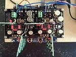
here's a quick few pictures to explain how I've mounted my shunt regs on my dac board. It sounds great and I'm satisfied that this is pretty much as good as the placement can get.
Apologies for the crappy diagrams, I only have my phone with me and very limited Internet access this week, so I've had to make do....
I've mounted the shunts as close to the DAC chip as possible, as per Guido's instructions for best results. In the diagram, light pink is v-in, dark pink is v-out and orange for gnd. I have used the original places for the Wima film caps, as the shunt regs have Wima caps on the output anyway. I wasn't happy that the 8v reg was as close as it could be to all 3 places where the DAC used it, so I cut a couple of tracks and added wire jumpers to make a nice short path for all 3. I've kept the film caps in place for the further 2, but I guess it's questionable as to whether these are needed.
Red on the diagram is where I've cut the tracks and green is where I've added tracks with small wire bridges, but I don't have a picture of that as it's mostly on the underside of the board.
I've removed all the electrolytics around the DAC chip apart from the 2 for the v-com as they work differently and are coupling as apposed to decoupling.
The only way I found (thanks to Stefan for the inspiration) to fit the 8v analog shunt reg in this position was to not use 2 of the output wires (A pos and A neg) that go down to the main board and use that space instead for the shunt board. If you look at the circuit for the main board, these wires are immediately joined anyway, so there's no real difference joining them on the DAC board this way. The newer dac boards have this as an option on the boards, but mine is the older design, so I replicated the same functionality using small wire bridges underneath.
Hopefully this makes sense. let me know if you have any questions, but bare in mind I'm mostly 'off grid' for the next few days.
")