I just got a 1706 from burr brown. My first reaction was wholly how am I supoed to solder this???? The leads are so close together that I can hardly get a sheet of paper in-between them. This surface mount stuff always looks bigger in pictures. One of my teachers suggested rubbing solder all over the leadS then heating it to make it stick to the PCB and then removing the solder by pulling it away with the soldering iron. I am skeptical that this will work. I hope the SCIC package is bigger then the SSOP.
LBHajdu said:I just got a 1706 from burr brown. My first reaction was wholly how am I supoed to solder this???? The leads are so close together that I can hardly get a sheet of paper in-between them. This surface mount stuff always looks bigger in pictures. One of my teachers suggested rubbing solder all over the leadS then heating it to make it stick to the PCB and then removing the solder by pulling it away with the soldering iron. I am skeptical that this will work. I hope the SCIC package is bigger then the SSOP.
Over at the Seattle Robotics site, here is an article on SMT soldering using water based solder and a <B>toaster oven</B>.
Have You Seen My New Soldering Iron? - Kenneth Maxon
liquids
Hi Leve,
I always solder those devices with 1/40" spacing with silver
solder (extra thin) and a flux liquid put on all pads this makes
very professional looking solder joints and prevents the silversolder from making shortcuts. Of course you have to use
a high grade soldering iron with very fine tip. I use a metcal
professional station (got it as surplus from my company)
Uli")
LBHajdu said:I just got a 1706 from burr brown. My first reaction was wholly how am I supoed to solder this???? The leads are so close together that I can hardly get a sheet of paper in-between them. This surface mount stuff always looks bigger in pictures. One of my teachers suggested rubbing solder all over the leadS then heating it to make it stick to the PCB and then removing the solder by pulling it away with the soldering iron. I am skeptical that this will work. I hope the SCIC package is bigger then the SSOP.
Hi Leve,
I always solder those devices with 1/40" spacing with silver
solder (extra thin) and a flux liquid put on all pads this makes
very professional looking solder joints and prevents the silversolder from making shortcuts. Of course you have to use
a high grade soldering iron with very fine tip. I use a metcal
professional station (got it as surplus from my company)
Uli
to solder smds , you don´t have to solder the pins separately.
Solder the whole side of the IC without overheating it. the whole side will be short circuited but dont worry yet. Using a solder wick or a special tip suck the solder out again. the pins stay soldered but you have to be sure no solder is in between the pins. I do this everyday, so it works for sure. I solder 160 and 200 pin ICs so no problem for such a small IC.
Solder the whole side of the IC without overheating it. the whole side will be short circuited but dont worry yet. Using a solder wick or a special tip suck the solder out again. the pins stay soldered but you have to be sure no solder is in between the pins. I do this everyday, so it works for sure. I solder 160 and 200 pin ICs so no problem for such a small IC.
I just had an idea. Many Threads have been submitted on the forum about building a Dolby Digital decoder. All of them have ended in failure for the reasons : you need some type of document from Dolby just to buy these chips, you need a microcontroller to run the chip, and the schematic for it is huge. While I was on the net I fount this little device. It’s called the External DD5.1/DTS Decoder, Jazz Speakers DE-005. It’s made for a computer MM system. It uses the Dolby Pro Logic/Dolby Digital/MPEG2 stereo/DTS decoder CS4926 04 CL from Crystal Semiconductor. I don’t have a price for this thing, but it can’t be very costly, my guess would be about $150. So what’s to stop us from tapping the Pins of the CS4926 and stealing the PCM output of the decoder and sending in to the front and of the DAC where working on ??
Attachments
oops
uli said:Hi Leve,
after looking at www.crystal.com/products/[(url] and...ilr: :devilr: [url]www.crystal.com/products
Uli
It looks like i guessed the price just right. Exactly $150 and that was just a guess at the time. I’m still looking for a better solution. If money where no object I would go with the MDP-3X MULTIPLE DIGITAL PROCESSOR from http://www.msbtech.com/ . It comes with a decoder and 3 PCM outputs right on the back so I don’t have to do any work. Why couldn’t more makers of DVD players think of that? However its way over priced.
My first choice for a 20bit or 18bit dac is still the very highly regarded PCM63.
My first choice for a 20bit or 18bit dac is still the very highly regarded PCM63.
obsolete
Hi Leve,
the PCM63 is obsolete
BTW cost no object: PCM1704 in 20bit mode!(just one pin hi/lo)
but for home cinema (noise) 6x PCM1704 it´s overkill.
Uli
LBHajdu said:My first choice for a 20bit or 18bit dac is still the very highly regarded PCM63.
Hi Leve,
the PCM63 is obsolete
BTW cost no object: PCM1704 in 20bit mode!(just one pin hi/lo)
but for home cinema (noise) 6x PCM1704 it´s overkill.
Uli
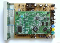
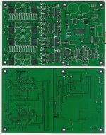
This is the PCB.
The project was more a "proof of concept" and a test if I can get it running, not to be the ultimate DIY DAC. But i tried to use most information and tips I found, except about special oscillator circuits. Just one thing at a time
Short description: optical receiver TORX176, receiver TI DIR1703 switchable between coax and optical input, next step is the Analog Devices AD1896A Sample rate converter to upsample to 96kHz. It feeds the TI DF1706 digital filter to drive four PCM1704 DACs for balanced output. I/U Conversion is PASS D1.
Voltage regulation for digital part (3.3V, +- 5V) is on board, +-30V for output stage has to be supplied. I use one of my ONO power supply boards, which gives a nice regulated +-30V.
There are two errors in the layout. one trace between the two rectifier bridges has to be cut, and I forgot to place the output caps of the D1 stage. But otherwise it seems to work nice, and it sounds fine.
I will not make another large group buy from this, like the ONO, VERY limited time this year on, but I have left seven of this boards. I ordered ten pieces. If there is any interest, please email. But because of time, I can not give much support beside schematics. You should know what You are doing, and be able to read and understand the data sheets of the used parts.
-Peter
Attachments
Re: DAC working!
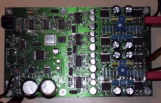
Of course the DACs are PCM1704 !
pquadrat said:Some postings above I was writing about a DAC with PCM1702 and Pass D1 output stage. I have finished it now:
Of course the DACs are PCM1704 !
pquadrat said:
I will not make another large group buy from this, like the ONO, VERY limited time this year on, but I have left seven of this boards. I ordered ten pieces. If there is any interest, please email. But because of time, I can not give much support beside schematics. You should know what You are doing, and be able to read and understand the data sheets of the used parts.
-Peter
This is just what I was looking for; I'm definitely interested in one of these boards. I sent you a message.
pquadrat said:This is the PCB.
I will not make another large group buy from this, like the ONO, VERY limited time this year on, but I have left seven of this boards. I ordered ten pieces. If there is any interest, please email. But because of time, I can not give much support beside schematics. You should know what You are doing, and be able to read and understand the data sheets of the used parts.
-Peter
Hi Peter,
how much do you charge for 1 board (incl. schematics)?
Uli
Re: DAC Board
Price for one of these boards is EUR 30,-. A power supply board from the Ono for the +-30V is EUR 25,-, but You can easily build Your own PS.
I have more than 7 askings for the boards now, and will sell to the first seven orders. But please only one board per order.
I have emailed You directly.
I have emailed You directly.
Exactly two! Looks harder than it is.
I have emailed You directly.
I have emailed You directly.
Price for one of these boards is EUR 30,-. A power supply board from the Ono for the +-30V is EUR 25,-, but You can easily build Your own PS.
I have more than 7 askings for the boards now, and will sell to the first seven orders. But please only one board per order.
Sparhawk said:
This is just what I was looking for; I'm definitely interested in one of these boards. I sent you a message.
I have emailed You directly.
blank527 said:Hi,
I mailed you before, but i'm not sure wether it came or not.
Hence this reply.
Nice DAC you have buid there!
How does it sound?
I would be (very) interested in buying a PCB from you, since you got spare left.
How much does 1 PCB cost?
Thank you,
Remco Blankesteijn
I have emailed You directly.
moe29 said:i bet that took more than an afternoon
to solder up!
verrry nice
-------------
moe29
-------------
Exactly two! Looks harder than it is.
Apogee said:Peter,
Nice Job!!!!
I too would be interested in purchasing one of the boards...
I sent you a message via email.
Thank You!
I have emailed You directly.
uli said:
Hi Peter,
how much do you charge for 1 board (incl. schematics)?
Uli
I have emailed You directly.
- Status
- This old topic is closed. If you want to reopen this topic, contact a moderator using the "Report Post" button.
- Home
- Amplifiers
- Pass Labs
- A nice dac to complement the Aleph-X.