qusp:
One board is indeed balanced stereo output, and I've tried to include everything on board so all that would be needed is a pair of small transformers to make it all functional.
cool, well yeah just put me down for 2 at this stage, if you get extras and it looks like selling out i'll reassess that at that time. so am I to take from the above that you would be lowering the supply voltages from +/-50vdc? or have you already done that along with other tweaks to keep the same type of excellent performance as with the FQA32N20 at this rather extreme measure but at lower Vs?
I'll look into your suggestion for under-board mounting of the resistors and transistors, which might actually work for this setup. I'm used to bolting down through the PCB and pinching the transistor between the PCB and the heatsink, but that wouldn't work in this case since both the resistors and the transistors have very different thicknesses. Bolting them down first, and then mounting/soldering the PCB might work well though, and if I place holes at the correct locations, then it might be possible to get everything off without having to de-solder.
yep it works rather well like that and if you have room for onboard sinks, you have room for the holes in the right place.
I agree with you that the right hand side is the more logical layout, so I'll probably go with that. I'll get rid of the output XLR connector and just come off with a header since having outputs on the side is a little lame. People can wire up their own output connectors, and that leaves more room for output coupling caps.
haha cool, glad you said it, off the sides might be good for breadboard mounting with no case, but would make for a bit of a strange casing
 dont suppose you would consider a servo and DC coupling?
Looks like we're up to between 15 and 20 boards, so I'll probably put in an order for between 30 or 40 to start. Maybe a group buy for the transformers would be in order as well. I'll look into it.
yep and maybe sand as well? wonder if someone would donate some R100 for testing
I do indeed have provisions for an adjustable 5V reg for the DAC itself, I have all three standard digital input formats (SPDIF, AES/EBU, Toslink) with a 6 pin header to select the desired one (could be wired to a switch).
I would add open as well, so someone could wire up a USB to i2s and have it connected when open if that makes sense, looks to me like you are using spdif input rather than 2s from those? ahh no thats right that wont work with the buff as it requires the onboard dip switch to be flipped to PCM.
the ackodac presents a bit of a problem for stacking like the buff due to the 7 discrete regs that it stacks on top of already, but it can still work with an intermediate layer of lexan or delrin or something, which is how I was planning on doing it for final layout anyway. it will work some way, if not as straight forward as the buff due to the rather involved power supply arrangement.
I'd be shocked if those JFETs had higher transconductance than the FQA32N20's. I measured 0.922 S with 130mA and 25VDS where the Toshiba looks like it'll be around 0.5 S (kudos to Toshiba for actually putting Yfs on the datasheet)
me too, others in the ZEN thread have said the inputZ problem can maybe be solved by paralleling the JFETs, but I do not believe this is a solution at all. that table you made of all the devices illustrated so plainly the effect of transconductance on the sabre
Hi Guys,
Keep it coming! I've started a list, and things are looking pretty good. There will be a minimum of 30 boards, and if I can push it up to 50 then the pricing will be even better.
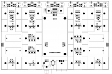
I've attached the rough layout for the entire PCB, so people can comment and make any suggestions. There's also a pdf which is to scale, so you can print it out and get a better idea of size. No routing done yet, but I'll probably get around to it tomorrow.
I priced out a few different options with a few different manufacturers, and it's looking like Advanced Circuits is the best so far. If I fill out an online quote for 30 pcs of 50 sq. inch 2-layer board, they come out to about $22 each.
Both of the other suggestion came out to be quite a bit more, but I think it's just because the board size is rather large. Gold Phoenix PCB works out to $33 per board ($99 for 150sq. inches).
I also looked into 4 layer pricing, but it almost doubles the price of each board. I'll do my best to route it on two layers, but it's not going to be easy with the top mounted heatsinks making it impossible to have anything but a ground plane on the top layer.
Possible group buy items include:
- Transformers from Antek:
Antek - AN-0240
They're $11 each - 2 x 38.4VAC with 480mA current draw, which should give about 53.5VDC. I'm using +/- 45VDC regulated which is about perfect. You could probably get away with +/-50VDC as well. They're 25VA, and the circuit needs about 21VA. I don't like over-sizing transformers for low level circuitry, so I'd rather be at 84% capacity with a 25VA than 42% with a 50VA. Any comments here are welcome, and there is a 50VA version for $13 if people prefer that.
- Heatsinks from Digikey:
Digi-Key - HS350-ND (Manufacturer - 529802B02500G)
There's a significant discount for these at 100pcs. Anyone know of a cheaper source? Most manufacturers make this style of heatsink.
Cheers,
Owen
Keep it coming! I've started a list, and things are looking pretty good. There will be a minimum of 30 boards, and if I can push it up to 50 then the pricing will be even better.
I've attached the rough layout for the entire PCB, so people can comment and make any suggestions. There's also a pdf which is to scale, so you can print it out and get a better idea of size. No routing done yet, but I'll probably get around to it tomorrow.
I priced out a few different options with a few different manufacturers, and it's looking like Advanced Circuits is the best so far. If I fill out an online quote for 30 pcs of 50 sq. inch 2-layer board, they come out to about $22 each.
Both of the other suggestion came out to be quite a bit more, but I think it's just because the board size is rather large. Gold Phoenix PCB works out to $33 per board ($99 for 150sq. inches).
I also looked into 4 layer pricing, but it almost doubles the price of each board. I'll do my best to route it on two layers, but it's not going to be easy with the top mounted heatsinks making it impossible to have anything but a ground plane on the top layer.
Possible group buy items include:
- Transformers from Antek:
Antek - AN-0240
They're $11 each - 2 x 38.4VAC with 480mA current draw, which should give about 53.5VDC. I'm using +/- 45VDC regulated which is about perfect. You could probably get away with +/-50VDC as well. They're 25VA, and the circuit needs about 21VA. I don't like over-sizing transformers for low level circuitry, so I'd rather be at 84% capacity with a 25VA than 42% with a 50VA. Any comments here are welcome, and there is a 50VA version for $13 if people prefer that.
- Heatsinks from Digikey:
Digi-Key - HS350-ND (Manufacturer - 529802B02500G)
There's a significant discount for these at 100pcs. Anyone know of a cheaper source? Most manufacturers make this style of heatsink.
Cheers,
Owen
Attachments
I was thinking the same thing, was just about to print it out to see. without that ability and with them all so close around the board like that, it also makes it impossible to do anything with the ackodac unless its elevated up over the heatsinks, which is not at all ideal for both noise and all the heat rising up past the dac. such small sinks will be a bit toasty too would they not? the sigma22 I posted uses oversized heatsinks with the flanges (or whatever they are called) flared much more, so the hole exists within the profile of the sink, but with these smaller sinks and larger devices, I doubt it'll work
Last edited:
Please excuse me Owen, if i'm out of order here ....
I'm a bit puzzled with the layout and perhaps there is a good reason for using all those seperate heatsinks and long tracks, and combined signal earth and power supply 0volt tracks ....
Would it not be better to thermally connect the active devices together on one heatsink and reduce the track lengths to the minimum possible?
And perhaps collect all the regulators onto another common heatsink at one end of the pcb (or maybe a seperate board)....
Perhaps this would also reduce the size of the final design?
Hi Guys,
Glad to hear people are in for the 4-layer if it's needed. I'll see what I can do with 2 layers, but I too would gladly pay another $20 for a better overall layout. We'll see where it takes us.
qusp and neb001:
You guys both have valid points about the tight heatsink spacing, but even with minimal airflow it should be alright. At +/-45 volts there is 2.7 watts dissipation on the top resistor, 2.4 watts on the mosfet, and 5.5 watts on the lower resistor. The resistors can run hot without any problems, it's the fet that needs to stay cool. With only 2.4 watts on that sink, at worst case 4 or 5 degrees C/W, it's not going to run that hot. I could certainly add venting to the PCB below the fins on the heatsinks, which might help a bit to keep things cool.
qusp: Could you tell me what the board size is for the ackodac? Like I said, I can certainly try to accommodate it, but I don't have one here to measure. Does it have a million little daughter boards hanging off all sides? Maybe a picture along with some rough dimensions would be best.
jameshillj:
You're certainly not out of order at all, any comments are welcome. I did say above that the top layer was a ground plane, but I should have said "ground layer". I won't be combining all the grounds together as that would cause a ground loop / hum disaster.
I've been pushing for the smaller on-board heatsinks since it takes some of the guesswork out of the process, and allows a stand-alone PCB to work the way it is, without having to bolt a dozen different parts off-board to various heatsinks. On the the other hand though, it does waste PCB space like you said, and the airflow will be quite poor compared to side mounted heatsinks. Tracks are also a little longer, but you'll find that even with the parts side mounted, the tracks are pretty long.
What I can do is try a rough layout without the on-board sinks, the regs along the top of the board, and the fets/resistors along the side. I'll see how much space it can save, and how the routing looks. If it's significantly better, then we can go with that.
Cheers,
Owen
I can do better than that, I can give you a PDF with the layout. send me an email through the forum and i'll reply with it. will also send you some pics of another build in progress on the breadboard, as mine is a bit chaotic at the moment as I have just received the advanced MCU requiring a rework of the layout and I will be receiving a crazy oven controlled XO shortly to evaluate and i'm preparing a power supply for it , but you'll get the idea with the one in progress combined with the plans.
the ackodac stacks from above on top of 6 discrete regulators via pin headers (2 of which are duals), there is a reg for each sabre supply. anyway you'll see what I mean. they are fairly compact, but enough to cause issues if you wanted to stack directly on top. I would be ignoring the D1's power supply for the dac, all I need is some way to mount the lexan platform above and a logical header for connecting the analogue ins from above, shouldnt be too hard to work it out, but I do need to be able to use the floor as a sink if possible, otherwise I would be a bit worried about the completed height of the stack; saves money too and the holes can double as ventilation
the ackodac stacks from above on top of 6 discrete regulators via pin headers (2 of which are duals), there is a reg for each sabre supply. anyway you'll see what I mean. they are fairly compact, but enough to cause issues if you wanted to stack directly on top. I would be ignoring the D1's power supply for the dac, all I need is some way to mount the lexan platform above and a logical header for connecting the analogue ins from above, shouldnt be too hard to work it out, but I do need to be able to use the floor as a sink if possible, otherwise I would be a bit worried about the completed height of the stack; saves money too and the holes can double as ventilation
Last edited:
opc,
The heatsink spacing can maybe be addressed in a diferent way:
Why not place only 1 heatsink per side and turn the board upside down with the transistors and regulators screwing through holes on the PCB ?
The Heatsink would be on top so thermal coupling and dissipation would be optimum.
Also board size would maybe be a bit smaller and tracks shorter.
I'll make a simulation later today...i'm at my regular work now ( lunch-time ) so cannot spend more time on this.
Last edited:
Yeah Owen, multiple plug in boards are a real pain in the A!
If the final cct is the one on post #193, then if you group all 4 fets in the centre with a common sink, you can simply (?!) fit the + and - regulators on the "top" and "bottom" sides of the board with another 2 common sinks and the major part of the top (gnd) plane can act as the power supply central 0v, with the signal 0v kept seperate inside that.
On the power supply, I would think about using a much smaller o/p electro (if any) and have the 1 x 10uF as the supply "o/p" cap to the cct - unfortunately, most of the good 10uF caps are physically large, but you can always stand them up vertically.
Curiously, John from EC Design on the 1541A thread has found the Monacor MKT caps to be first class for signal, so possibly also good as p/supply o/p too, and they have reasonable footprint ...
well, perhaps leave the option there as not everyone will agree about this, but a 100uF cap should be sufficient for the job and they all have similar holes (Nichi KZ, Silmic, BG F/K, Pana, etc)
Another suggestion, as you have enough voltage, perhaps add a Cmultiplier after the main ripple caps before the regulator - something like the "Teddy-Regs" cct will not only get rid of some line noise, but also boost the performance of the regulator quite a bit.
Hopefully, you won't need a 6.8uF signal o/p cap - a 10kR load for a 4Hz hipass is about 4uF, a much smaller option, and bipass caps (if required) can be added underneath.
Why a 4 layer board - 2 layers should be enough, with maybe a link or 2?
hope this 2 cents is of some use ....
- Status
- This old topic is closed. If you want to reopen this topic, contact a moderator using the "Report Post" button.
- Home
- Source & Line
- Digital Line Level
- A New Take on the Classic Pass Labs D1 with an ESS Dac