.. hm ungapped iron powder cores?
They seem to be popular for class D output filters, but I am wondering about the distorsion behaviour.
I did never analyze in detail, but from first glance I would prefer some gapped ferrite.... or may be some gapped Cool-u... or (high end) cut cores of amorphous metals like Vitroperm from VAC....
On the other hand - using up, what you have on hand is a good attitude. I tend to do so also.
Hi ChokoHolic
Here is an old post where I discovered what Fedo is talking about")
http://www.diyaudio.com/forums/showthread.php?postid=926467#post926467
It works because the two coils are buildiing on the same magnetic field in the core.
Here is an old post where I discovered what Fedo is talking about
http://www.diyaudio.com/forums/showthread.php?postid=926467#post926467
It works because the two coils are buildiing on the same magnetic field in the core.
That's right Baldin!
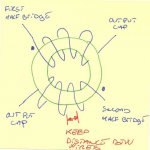
That's the way to minimize output coil! Half inductance for each winding, lower loss, smaller coil! You can push out near 6Kw on a T206-2 core, with only 14 turn of 10 gauge litz wire. Your current capacity will be 40A continuous (coil coolled) with dual 24uH inductance. Just keep in mind that winding technique is important. Winding should be continuous circular with 180 degree out of phase signal. That's means at first side of the toroid 1 wire to first half bridge, second wire to output capacitor, second side of coil first wire to output capacitor and second to the other half bridge. Dont forget to put isolating piece between each winding to avoid short if wire coating melt. With a piece of T206-2, with sufficient air cooling, core temp did not exced 25 degree more than ambient. Expect lot less a lower power. I never try it with solid wire, not equiped to wind-it, if someone try, let me know!
Another try....Someone have ever try this configuration on single ended amplifier? What I means is to put one winding to the 0V and put the output capacitor on the other side of the dual winding? Maybe lot better for EMI, at the loss of common output ground, what is not a major issue for home amplifier..
Fredos
Is this what you mean? (See picture)
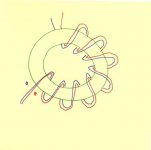
Why is it better to use separated windings on the two halfs of the core, in the H-Bridge, instead of winding to two together. As I see it the coupling will be even better, and the voltage on all windings being next to each other, reducing the capacitance. (Se next picture.)
For a single ended amplifier I don't see the gain. As you don't have the two out of phase signals, it will just act as a normal coil, with the same number of windings as the two windings put together.
Attachments
ChocoHolic!
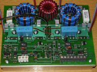
There is more variant of this amp, in the latest one I used 2*2 pcs of Arnold MS130060-2 with 7 turns (5 uH). I attached a picture of it. I must admit that my inductors starts to saturate at highest current, but this is not normal operation. A found that these cores starts to distort at 440 A*turns, so 60 Ap is the quality limit. This was not the best solution. Now I'm going to use E42 gapped (3mm) ferrite instead.
Tekko!
I'm not Rotchild, just a student! I have to work for 4 days for the price of 4 of the lowest Rds available FET. But you don't really need the one with the lowest resistance. Vdd=60 V in full bridge means 700W @2 ohm, and for this 4*2 IRF540N (or 4*1 FDP3652) is oversized. I can send them to you if you write your address.
There is more variant of this amp, in the latest one I used 2*2 pcs of Arnold MS130060-2 with 7 turns (5 uH). I attached a picture of it. I must admit that my inductors starts to saturate at highest current, but this is not normal operation. A found that these cores starts to distort at 440 A*turns, so 60 Ap is the quality limit. This was not the best solution. Now I'm going to use E42 gapped (3mm) ferrite instead.
Tekko!
How about you send me four of the fets with the lowest Rds(on) that exists there where you live ?
I'm not Rotchild, just a student!
I have to work for 4 days for the price of 4 of the lowest Rds available FET. But you don't really need the one with the lowest resistance. Vdd=60 V in full bridge means 700W @2 ohm, and for this 4*2 IRF540N (or 4*1 FDP3652) is oversized. I can send them to you if you write your address.Attachments


Baldin said:Is this what you mean? (See picture)
Why is it better to use separated windings on the two halfs of the core, in the H-Bridge, instead of winding to two together. As I see it the coupling will be even better, and the voltage on all windings being next to each other, reducing the capacitance. (Se next picture.)
For a single ended amplifier I don't see the gain. As you don't have the two out of phase signals, it will just act as a normal coil, with the same number of windings as the two windings put together.
Hi Baldin, Fredos,
...yes that's the configuartion which I mentioned to save factor 1,41 (but never factor 4 !).
And Baldin is also pointing out the key. These two windings do magnetically exactly act like one winding with double no of turns.
Two windings with 10uH each on one core will behave in the filter like two separate cokes with 20uH.
The benefit of this construction is just that you use one larger core instead of two smaller. One larger core is offering the more fortunate ratio of Ae vs. turn length, because Ae is increasing by the square of size, while the turn length is only increasing linear with the core size. So one larger core is fortunate vs. two in series connected chokes.
The arguement that the inductance is increasing by square of turns and by this would help to reduce the required number of turns is not valid, if we consider flux density and core saturation.
Example:
Instead of 2x14 turns on a T206-2 you could use two torroids with the same Ae but double AL-value and wind 14 turns on each. This would result in the same flux density. From size we would need two cores of same Ae but would need less space for the winding. ==> Difference in size is definitely below factor 2. Not at all 4.
Nevertheless this coupled inductors are saving space/costs/losses in a remarkable way . It is the old story about using several chokes in series or one larger sized type. Just assume a square root function from the number of chokes, which you replace by a single single core design....
BTW: Twin winding with 24uH each... means effective 96uH... with 40A ... and a T206 may have a magentic cross section around 135mm^2... ==> You would have to chase your choke up to 1Tesla or say 10^4 Gauss to provide 100% inductance at 40A ! ... I guess it will still have some inductance there, but it cannot be linear anymore with normal iron powder materials....
Hi ChocoHolic
I don't think it has anything to do with the core being larger.
If you take two cores of the same type and size, and get say 10uH on each by making X windings.
If you now take only one core (same as before) and makes 2 times x windings you'll have 2 times 20 uH in an H-bridge!
You can do a simulation to verify (using a transformer of 1:1 as the two coils) .... I know I had to
When I said it would be the same as just two coils in series, I was refering to the single ended case.
I'll try to do a simulation ... later
Baldin said:Hi ChocoHolic
If you take two cores of the same type and size, and get say 10uH on each by making X windings.
If you now take only one core (same as before) and makes 2 times x windings you'll have 2 times 20 uH in an H-bridge!
Yes of course. But the allowed current without saturation will be half then. To avoid this you would have to adjust the core parameters and/or number turns.
There is no way around the unpleasant truth of:
B= (I x L) / (N x Ae)
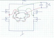
Dont forget in your calculus guy that PWM square wave current will cancel each other and the current of the modulated signal are in phase (audio), so their is no (theorical) way to saturate the core with the peak current....I dont know if nobody have think about that....That's why I suggest you to use core in that way! If you parrallel winding like in the second picture, booth current will be out of phase, saturation will happen. You have to drive this coil with same phase PWM with opposite phase audio.
Fredos
Fredos
- Status
- This old topic is closed. If you want to reopen this topic, contact a moderator using the "Report Post" button.
- Home
- Amplifiers
- Class D
- A new (Stupid?) class d idea