the current of the modulated signal are in phase (audio), so their is no (theorical) way to saturate the core
I'm not sure how do you mean this. If audio current is in phase, (having taken account choke winding directions), then magnetic fields are summing (this is the reason of increased inductance), so it can be driven to saturation easier. Carrier signal never have enough current to saturation, you don't have to deal with it. The important thing (in saturation) is audio current.
You must think of a different phenomenon! In case you connect audio out of phase to two weakly coupled windings (one half of core for one half bridge, ...), then saturation really needs a much higher A*turns product. But then you must have much more turns to achieve enough inductance, because differential inductance is only due to leakage. This way you can get a high common mode inductance, wich results a very low current at switching freq. But an unpleasant side-effect: some harmonics (2*fs=fseffective!) of switching freq is out of phase, hence their induced magnetic field steps out from core (just like audio signal). In this arrangement core can be much smaller, because most of magnetic energy stored in air, instead of iron core. I hope I explained it clearly.
I agree with ChocoHolic with a little addition: In the two cases we can have unchanged core material (as he assumpted inplicitly), or unchanged number of turns. With unchanged number of turns Al at common chokes is half of the one at separate chokes, so it can bear the arising twice A*turns with the same dimensions. Summary: reduction in size of core can be achieved by less permeability (or higher Bmax, but if it is already the highest, then nothing to do with it).
Attachments
Hmmmm, I think I'm getting (even) more confused now
Think I'l still go for the two windings wound together on a single core (T130-2), using banking method, to reduce capacitance.
Pafi
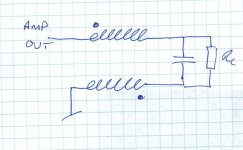
In your construction, what filter are you using?
It seems to be a full bridge with two separate blue coils for each half (think you said 5 uH each). But you have an additional coil in the middle. Are you using 4. order filtering or is the last coil a common mode filter?
By the way ..... 5 uH seems very little ... what switching freq are you using??
Think I'l still go for the two windings wound together on a single core (T130-2), using banking method, to reduce capacitance.
Pafi
In your construction, what filter are you using?
It seems to be a full bridge with two separate blue coils for each half (think you said 5 uH each). But you have an additional coil in the middle. Are you using 4. order filtering or is the last coil a common mode filter?
By the way ..... 5 uH seems very little ... what switching freq are you using??
Pafi is correct. If the windings on a single toroid are such that the magnetic currents oppose each other there will be a net magnetic current of 0 through the core. If the windings are such that magnetic currents are in the same direction then they will add and can make the core saturate earlier.
Since the two windings will share the same flux, they will also be forced to have very similar currents flowing through their windings at the same time. This is beneficial for a bridged output topology because you want the same current flowing out of the one half bridge to flow back into the other half bridge.
Since the two windings will share the same flux, they will also be forced to have very similar currents flowing through their windings at the same time. This is beneficial for a bridged output topology because you want the same current flowing out of the one half bridge to flow back into the other half bridge.
...or is the last coil a common mode filter?
Yes, it is.
2*5 uH=10 uH with Rload=2 ohm is quite usual. fsw=160 kHz, but I use 3 level (BD) modulation, so effective freq is 320 kHz, and diff mode carrier voltage is (maximum) half of the one at 2 level modulation.
Hi Pafi
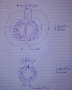
I think your drawings explain a lot. Thanks.
To me it seems that this kind of winding method will produce a lot og stray magnetic field, which will likely couple into sensitive areas of the amp!
Fredos: How do you cope with this in your design?
I mean you are running at very high current levels, and hense must have a very high field.
(the winding technique I'm refering to, as two coils wound with tight magnetic couplings, I think is commonly known as "bifilar", and is often used in common mode filters)
Think I'll try to find a good book on coils/winding techniques/transformers/chokes etc. ....... there is a lot to be learned
Even if I agree that the HF component of the flux density is usually low. Say about 10% of the max. load current... Why should they cancel out in the choke? In most designs the HF of both half bridges is invers, in the same way as the Audio signal. (...probably just very few special designs run them in the HF in common mode and modulate the Audio signal by phase shift...).
Pafi:
In your proposal of opposite polarities... yes, I think it would behave like you describe. But why should someone do this? As you describe the resulting effective inductance will be the leakage inductance only, means it will be quite low and you would need quite a lot of turns to get the desired inductance value. Just from feeling, then I would prefer a torroid air coil with both windings wound to sum up...
Some radiated field is of course also happening in the air torroid. But in your proposal the entire field would close its loop outside of the winding.
I have another concern: Some months back I have been thinking about the exactly this topic: Coupled output inductors or separated coils? I did not dare to go for the coupled design because for me it is not clear how it would influence the two half bridges. Basically both half bridges run inversly. But due to some individualism there will always be some nano seconds difference for the switching. The voltage change, which we switch to one winding will of course be reflected on the other winding and will be seen from the other half bridge.
Also the fields in the choke would not fully add up any more, because some portion of the current would be bypassed to ground by the one cap of the output filters.
Please note: My outputfilter would have two capacitors in series, -with their center point at ground. For the filter function it would be of course sufficient to have just one cap in parallel to the speaker. But then the common mode HF signal of both speaker wires vs GND would be quite high. And the long speaker wires will radiate all that dirt in unpleasant perfection....
I think the effect the coupled inductors would not blow the amp (also not with my GND tapped filter), but I am not sure if it would fortunate or unfortunate or just meaningless for the switching behaviour of the half bridges.... So I decided to go the silly, but easy to understand path.
Hi Pafi
I'm using the exact same approach to achieve both common-mode filtering and differential mode filtering for SMPS in a single choke. My inductance values are also the same, 5+5uH for 17+17 turns wound on a 32mm OD ferrite toroid. The main disadvantage when this principle is applied to class D output filters is that the "differential mode" energy is istored in the non-coupled part of the inductance, which is the leakage inductance. In other words, all the flux lines due to "differential mode" current are flowing outside the toroid, yielding an air-cored behaviour.
I'm using the exact same approach to achieve both common-mode filtering and differential mode filtering for SMPS in a single choke. My inductance values are also the same, 5+5uH for 17+17 turns wound on a 32mm OD ferrite toroid. The main disadvantage when this principle is applied to class D output filters is that the "differential mode" energy is istored in the non-coupled part of the inductance, which is the leakage inductance. In other words, all the flux lines due to "differential mode" current are flowing outside the toroid, yielding an air-cored behaviour.
Eva said:Hi Pafi
I'm using the exact same approach to achieve both common-mode filtering and differential mode filtering for SMPS in a single choke. My inductance values are also the same, 5+5uH for 17+17 turns wound on a 32mm OD ferrite toroid. The main disadvantage when this principle is applied to class D output filters is that the "differential mode" energy is istored in the non-coupled part of the inductance, which is the leakage inductance. In other words, all the flux lines due to "differential mode" current are flowing outside the toroid, yielding an air-cored behaviour.
...good point. Seems like two separate choke have at least some advantage for common mode filtering.
I just measured my use-up-my-ferrite-scrap-chokes and got the following results:
- L = 42uH
- R_DC = 50 mOhms (I know, that's slighly high for my power, but thermal should be no issue, due to large surface)
- f_res= 7.8MHz (I will have to find out if this sufficient to avoid the blibs without RF-prefilter...)
- Saturation still unchecked. Theoretically around 60A.
- HF-losses neglectible since I changed the wire to litz-wire. First I tried solid wire and got roughly 10C temp increase at idle situation (+/-3Ap at 100kHz) due to the eddy current losses caused by the leakage field of the airgap . With Litz wire there temperature increase is not measurable for me, my thermometer has a resolution of just 1C.
But why should someone do this? As you describe the resulting effective inductance will be the leakage inductance only, means it will be quite low and you would need quite a lot of turns to get the desired inductance value. Just from feeling, then I would prefer a torroid air coil with both windings wound to sum up...
Why? One of the reason is this way we get high CMRR, and low idle current. Second: this way much more energy can be stored then in a simple toroid core, but significantly less wire needed then for an air core toroid. Air core toroids are very big. Eg.: 20 uH, A=2 cm^2, d=3 cm -> Al=1,2 nH/turn^2 -> 90 turns. There is not enough place for copper, and higher diameter means lower Al, so... Contrary to this a "common+differential" choke needs only about 2*22 turns on a 32 mm outer diameter core.
In most designs the HF of both half bridges is invers, in the same way as the Audio signal.
These circuits are out of date. In full bridge BD modulation is quite usual.
 Class D fashion is changing faster than I can read
 Is there a mayor disadvantage of the oldfashioned stuff?
Something that why I would call me silly for my first class D approach?
")
I love the simplicity of self oscilating hysteresis resonantors using a comparator with inverting and non inverting outputs in order to drive two half bridges....

There are many ways to get to the same place.
I don't think BD is winning nor loosing the competition.
I think the the different approches have advantages, and disadvantages, power handling, simplitity, PSU requirements, feedback topology etc.
I find that success is more tied to the actual implementation, PCB layout etc.
If we're talking about a drift, I think it is towards single ended design, or full chip implementation, rather than anything else. Seen the last modules from ICEpower?
http://www.icepower.bang-olufsen.com/sw2902.asp
(Single ended)
Topology is one thing, getting it to work and making it sound and measure well, is a different matter

To Tekko's original post
Would it be okay if a shorted gate smoked only a secondary side pulse shaper/driver stage? This is a lot more electronics, including another isolated power supply, and at least a few pF of parasitic load referenced to the power FET source and some more noise, amounts depending on your implementation. Depends on what your objective is. I tend to think everybody is out for maximum signal performance, A pulse transformer can get your drive level shifted in NOWnS compared to that IC. You could try a laser.
Would it be okay if a shorted gate smoked only a secondary side pulse shaper/driver stage? This is a lot more electronics, including another isolated power supply, and at least a few pF of parasitic load referenced to the power FET source and some more noise, amounts depending on your implementation. Depends on what your objective is. I tend to think everybody is out for maximum signal performance, A pulse transformer can get your drive level shifted in NOWnS compared to that IC. You could try a laser.
coupled inductor
Eva posted:
"
I'm using the exact same approach to achieve both common-mode filtering and differential mode filtering for SMPS in a single choke. My inductance values are also the same, 5+5uH for 17+17 turns wound on a 32mm OD ferrite toroid. The main disadvantage when this principle is applied to class D output filters is that the "differential mode" energy is istored in the non-coupled part of the inductance, which is the leakage inductance. In other words, all the flux lines due to "differential mode" current are flowing outside the toroid, yielding an air-cored behaviour."
In this case why Not use the air cored toroid? One problem with the iron toroid is the leakage inductance, and probably load capacitances, must be less symmetrical than with a well contructed air toroid, so wouldn't the resultant cancellation for the cored job actually be Worse?
- Status
- This old topic is closed. If you want to reopen this topic, contact a moderator using the "Report Post" button.
- Home
- Amplifiers
- Class D
- A new (Stupid?) class d idea