So if I understand you well you suggest me to do this LPF ?
Yesterday I bought this XO from Ebay
2pcs New for Kasun as 33c 3 Way 3 Unit Hi Fi Speaker Frequency Divider Crossover | eBay
Do you think It will be good ? if no I can use its inductors and modify it to your suggestion .
An externally hosted image should be here but it was not working when we last tested it.
Yesterday I bought this XO from Ebay
2pcs New for Kasun as 33c 3 Way 3 Unit Hi Fi Speaker Frequency Divider Crossover | eBay
An externally hosted image should be here but it was not working when we last tested it.
Do you think It will be good ? if no I can use its inductors and modify it to your suggestion .
I couldn't help myself and had to look at at least what your woofer is going to look like with that xo.
Chart 1: with 1.8mH
Chart 2: with 2.83mH + 15uF
Now if you look at chart 1 vs 2, you can see that there isn't much difference below about 1500Hz on the woofer so this isn't going to solve your lack of bass problem at all (the response will actually be going up a little bit around 800Hz!).
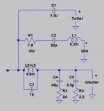
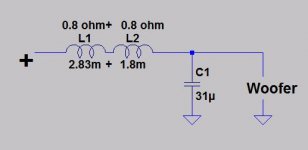
So here's what I think. Since the mid and tweeter work fine together, leave those old xo's alone except for adding resistance to bring their levels down. Now bastardize the new xo and put 2 inductors together and go 2nd order to get a response that is close to our target. Add a small 1uF cap in parallel this time to kill the 2.2kHz resonance and add a pseudo-zobel (parallel cap + resistor) to help to pull down the HF response of the woofer because that tanking 1uF cap forces it back upwards. So:
Chart 3: with 4.63mH (1.8 + 2.83)/1uF + 48uF (33 + 15)/24ohm + 5.5uF (2.2 + 3.3)/2.2ohm
Chart 4: the schematic
I think you'll need to run the woofer and mid in opposite polarity, so try reversing the connection on the woofer. Maybe (I'm guessing here) you may want to try a smaller value for C2 on the mid, say 15 or 20uF, if you think you are getting a little too much energy somewhere in the lower mids.
I don't know what resistance (L-pads?) you already have on the mid and tweeter but you should be able to just leave those as they are. As I said before, you can add resistance with R1 to the mid and tweeter together or you can do it separately before each one. Try 1.2ohm first from the new xo. But you also have old adjustable L-pads that came on the original xo's. Maybe you want to try those?
The xo you just ordered will have all the parts you need except for the 1uF cap and larger values for R1 if you need them. Best of luck.
Chart 1: with 1.8mH
Chart 2: with 2.83mH + 15uF
Now if you look at chart 1 vs 2, you can see that there isn't much difference below about 1500Hz on the woofer so this isn't going to solve your lack of bass problem at all (the response will actually be going up a little bit around 800Hz!).
So here's what I think. Since the mid and tweeter work fine together, leave those old xo's alone except for adding resistance to bring their levels down. Now bastardize the new xo and put 2 inductors together and go 2nd order to get a response that is close to our target. Add a small 1uF cap in parallel this time to kill the 2.2kHz resonance and add a pseudo-zobel (parallel cap + resistor) to help to pull down the HF response of the woofer because that tanking 1uF cap forces it back upwards. So:
Chart 3: with 4.63mH (1.8 + 2.83)/1uF + 48uF (33 + 15)/24ohm + 5.5uF (2.2 + 3.3)/2.2ohm
Chart 4: the schematic
I think you'll need to run the woofer and mid in opposite polarity, so try reversing the connection on the woofer. Maybe (I'm guessing here) you may want to try a smaller value for C2 on the mid, say 15 or 20uF, if you think you are getting a little too much energy somewhere in the lower mids.
I don't know what resistance (L-pads?) you already have on the mid and tweeter but you should be able to just leave those as they are. As I said before, you can add resistance with R1 to the mid and tweeter together or you can do it separately before each one. Try 1.2ohm first from the new xo. But you also have old adjustable L-pads that came on the original xo's. Maybe you want to try those?
The xo you just ordered will have all the parts you need except for the 1uF cap and larger values for R1 if you need them. Best of luck.
Attachments
Don't forget: we don't know what the actual sensitivity of the mid and tweeter are. Maybe they are at 88dB. Maybe they are at 90dB. Maybe they are at 84dB (but unlikely since your complaint is one of not enough bass). What you have to do is pull them down to a level that will match with the woofer with its new xo, about 85-86dB.
So, it's a trial and error kind of thing. And it's most likely that if you like the way the mid and tweeter sound now together, then you should bring both the tweeter and mid down together to match the woofer, not just the mid. So put R1 before both the tweeter and mid like in my diagram. But if you want to just start with the mid and leave the tweeter alone, then try that.
And again, I don't know what the old FR of the woofer was like and I don't know what the mid FR is like, so maybe C2 = 30uF on the mid will be fine. Maybe 20uF or maybe 15. You need to try them to see if they make any difference, good or bad, to you.
In regards to woofer polarity, the way that 2 drivers will sum together depends on the phase of the wavelengths. Adding more xo components changes the phase of the woofer, so I think you'll get a better response if you reverse the polarity on the woofer. Something like this is done all the time in 3-ways depending on their xo's. But as in all things audio, try it and see if you can hear a difference. If you can't, don't worry about it.
In the mean time I switched polarity to the woofers .
I think the bass now is tighter and quicker .
jReave What do you think about to use the ebay 3 WAY XO .
do you think Mod like this will be ok ?
I think the bass now is tighter and quicker .
jReave What do you think about to use the ebay 3 WAY XO .
An externally hosted image should be here but it was not working when we last tested it.
do you think Mod like this will be ok ?
Attachments

I read most of the entries. I hope this isn't redundant.
In a passive crossover, if you change the value of one part, it can throw off the accuracy of other parts in the circuit. In this topology, messing only with the woofer branch, doing anything to the woofer inductor will change the impedance from the point of view of the Capacitor. Beefing up the bass implies a boost at low frequencies, which implies reducing the effective efficiency of the woofer above the lowest freqs. So once you get the freq response you want on the woofer, now you need to attenuate both the mid and tweeter by whatever amount you boosted the low bass on the woofer. If an L-Pad is used and is not very precise in it's design, that will throw off the accuracy of the crossover components in the mid and tweeter circuits.
A much better approach is to put an EQ circuit ahead of the poweramp if possible. It can be a fairly simple passive circuit, or a full blown active EQ circuit, such as a Baxandall tone control circuit.
I will sum it to those who's not read the all thread .
I have Jensen system 500 speakers
I canceled the rear twitter and made it 3 way with XO like this
C1 = 3.3 u
C2 = 20 u (not 31u )
L1 = 0.2mH 0.17ohm
L2 = 1.75mH 0.8ohm
the original woofer got ruin . I replaced it with this dayton woofer
https://www.parts-express.com/dayton-audio-ds315-8-12-designer-series-woofer-speaker--295-434
overall I am satisfied from the bass but I would like to boost it more .
My room size is about 3.5 X 5 meter
I order from ebay this XO
2pcs New for Kasun as 33c 3 Way 3 Unit Hi Fi Speaker Frequency Divider Crossover | eBay
the schema is like this
jReave caculate how the dayton woofer will be with the eaby LPF XO
and it was like this
He suggest me to leave the ebay XO and to do mod to my XO look at his last posts
and my qeustion was maybe i can stay with the ebay XO and do mod like this
Baxandall tone control circuit looks like very nice option thanks .
if you check with speakers design sofware you will do it right
unfortunately i dont know how to use it . i tried couple of time but i got lost .
I have Jensen system 500 speakers
An externally hosted image should be here but it was not working when we last tested it.
I canceled the rear twitter and made it 3 way with XO like this
C1 = 3.3 u
C2 = 20 u (not 31u )
L1 = 0.2mH 0.17ohm
L2 = 1.75mH 0.8ohm
the original woofer got ruin . I replaced it with this dayton woofer
https://www.parts-express.com/dayton-audio-ds315-8-12-designer-series-woofer-speaker--295-434
An externally hosted image should be here but it was not working when we last tested it.
overall I am satisfied from the bass but I would like to boost it more .
My room size is about 3.5 X 5 meter
I order from ebay this XO
2pcs New for Kasun as 33c 3 Way 3 Unit Hi Fi Speaker Frequency Divider Crossover | eBay
the schema is like this
An externally hosted image should be here but it was not working when we last tested it.
jReave caculate how the dayton woofer will be with the eaby LPF XO
and it was like this
An externally hosted image should be here but it was not working when we last tested it.
He suggest me to leave the ebay XO and to do mod to my XO look at his last posts
and my qeustion was maybe i can stay with the ebay XO and do mod like this
An externally hosted image should be here but it was not working when we last tested it.
I am using the sound card EQ but is not enough . i need more power to the bass .A much better approach is to put an EQ circuit ahead of the poweramp if possible. It can be a fairly simple passive circuit, or a full blown active EQ circuit, such as a Baxandall tone control circuit.
Baxandall tone control circuit looks like very nice option thanks .
Yes of course I need some help from you guys how to design well the XOIn a passive crossover, if you change the value of one part, it can throw off the accuracy of other parts in the circuit.
if you check with speakers design sofware you will do it right
unfortunately i dont know how to use it . i tried couple of time but i got lost .
Attachments

Last edited:
That's not a bad idea. It's certainly easier to implement.
Below is what the woofer response will look like with the 2 inductors and 15uF. The 800Hz peak looks like it's still too strong and I'm not sure if the 2200Hz resonance is down enough, but it's worth having a listen too.
The problem however is that I have no way of knowing how the mid and tweeter response are going to turn out with the new xo?? Again, my thinking is that if you like the way they sound now, don't change them.
But try it. If you like it, then you are all set. If you don't, then take it apart and try it the way I previously suggested.
Attachments
Thanks thats a good news ") .
.
can you please try this chart again with 20uF cap instaed of the 15uF ? .
maybe this will cut above 800HZ .
if the ebay XO will lower than a little thats will be ok .I hope not too much .
.can you please try this chart again with 20uF cap instaed of the 15uF ? .
maybe this will cut above 800HZ .
well they sound good but i think too much louder than they should be .my thinking is that if you like the way they sound now, don't change them.
if the ebay XO will lower than a little thats will be ok .I hope not too much .
Yes 20uF is better than 15uF. You can probably go up to 30uF before the response at about 300Hz to 400Hz starts to peak and then you need to add resistance into the parallel leg to keep that down.
Chart 1 : with 15uF
Chart 2 : with 20uF
To try and help you see what might be happening, the next charts show you how your woofer might sum together with some random small mids.
Charts 3 & 4 : Summed FR with 4.6mH plus 20uF with 2 different mids showing how the 800Hz peaking would still be a problem with these mids. Your mid may or may not show something similar depending on its response but I expect it's going to be similar. However, it will probably sound better than what you have right now.
Charts 5 : Summed FR with a random mid with my proposed woofer filter that lowers the 800Hz and 2200Hz peaking. The peaking is gone and the FR is flatter right through to the higher frequencies. I'm hoping that you'll get a similar response with your mid.
Chart 6 : And just to show you, the same as chart 5 but with the polarity on the woofer reversed. A null is created at the xo frequency if the 2 drivers' phase are in good alignment.
Concerning the mid and tweeter and the pre-fab xo, I'm not sure that you understand that the new xo will be doing 2 things. It will be changing the actual xo slopes and probably the xo frequency, as well as adding resistance to bring their levels down. What I'm trying to say is that all you probably need is the latter which is just adding resistance before them. The change in the actual xo may end up being worse for the mid and tweeter but again, I don't have any way of modelling that because we don't have the FR or the impedance response for those drivers.
Attachments
-
 pic DS315 4.6 + 15uF.gif34.1 KB · Views: 34
 -
 pic DS315 4.6 + 20uF.gif34.1 KB · Views: 26
 -
 pic summed FR 2nd no tank no zobel.gif25.8 KB · Views: 28
 -
 pic summed FR 2nd etc w 2nd mid.gif25.3 KB · Views: 17
 -
 pic summed FR 2nd + tank + zobel.gif26.5 KB · Views: 26
 -
 pic summed FR 2nd + tank + zobel polarity reversed.gif27 KB · Views: 28
Chart 1 : with 15uF
Chart 2 : with 20uF
Charts 3 & 4 : Summed FR with 4.6mH plus 20uF with 2 different mids showing how the 800Hz peaking would still be a problem with these mids. Your mid may or may not show something similar depending on its response but I expect it's going to be similar. However, it will probably sound better than what you have right now.
Thanks . You did this charts with eaby XO ?
Charts 5 : Summed FR with a random mid with my proposed woofer filter that lowers the 800Hz and 2200Hz peaking. The peaking is gone and the FR is flatter right through to the higher frequencies. I'm hoping that you'll get a similar response with your mid.
This chart is the 1st order with the mod on the LPF that you suggest ?
Chart 6 : And just to show you, the same as chart 5 but with the polarity on the woofer reversed. A null is created at the xo frequency if the 2 drivers' phase are in good alignment.
Let me under stand . This chart is with null , as we can see a drop in total frequency respons at 500HZ -2000HZ .
This chart is done with straight polarity or reverse polarity ?
So you still suggest to reverse polarity on the woofers ?
Concerning the mid and tweeter and the pre-fab xo, I'm not sure that you understand that the new xo will be doing 2 things. It will be changing the actual xo slopes and probably the xo frequency, as well as adding resistance to bring their levels down. What I'm trying to say is that all you probably need is the latter which is just adding resistance before them. The change in the actual xo may end up being worse for the mid and tweeter but again, I don't have any way of modelling that because we don't have the FR or the impedance response for those drivers.
Can you please explain this again .
and if I will be use the ebay XO you suggest me to do another mod or two ?
Good questions.
Yes and no. Charts 3 & 4 are more or less with the ebay 2nd order woofer xo with the extra inductor added in and increased capacitor, so 4.63mH and 20uF. The mid, which is not your mid, so not the exact same response, only has a 20uF HP filter on it like your original xo. I'm using it just for the purposes of illustration.
It's the 2nd order that I suggested. So 4.63mH/1uF + 48uF/24ohm + 5.5uF/2.2ohm.
My mistake here. This one is with normal polarity. Chart 5 with the combination of 2nd order on the woofer and 1st order on the mid looks better with reversed polarity. What polarity you use on the woofer depends on which xo's you use on both the woofer and the mid. Use the recommended polarity with the ebay xo. If you go with my suggested xo, reverse the woofer polarity.
ok, the original speaker designers decided that given the mid and tweeter that are in the speaker, they sounded best with 1st order xo's. What I'm saying is that it may be best to leave this xo the same but that you just need to lower their SPL down to the level of the new woofer and its larger xo. So just add some resistance to the mid and tweeter.
The ebay xo on the other hand is 2nd order on all the drivers so now how the mid and tweeter sum together is going to be changed. It also has added series resistance to both the mid and the tweeter which should be good for your purposes, but notice that the values are not the same (2.2ohm for the mid and only 1.2 for the tweeter). So, 3 things can happen: maybe it will be worse, maybe it will be better and maybe you won't hear any difference at all. And there's only one way to find out since we can't simulate the response for those drivers and that's to try it out.
So, if you don't like it, maybe you can change the resistors on the ebay xo before the mid and/or tweeter to alter their levels but I'm not going to suggest that because maybe the problem is in the new xo's or maybe the problem is both the new xo's and the mid and/or tweeter levels (see, it's starting to get complicated). Instead, I think you would be better off going back to the original 1st order xo's on the mid and tweeter which we know sound good and just work on getting their levels correct to match the new woofer. Which is what I diagrammed for you a page back or so.
But notice the order I'm suggesting. Try the ebay xo first with the altered woofer filter. Might as well go with the easiest solution first. If that isn't pleasing for you, then do the extra work of mining the ebay xo for parts and creating the combination of new and old xo's that I've suggested and work on adding in the right resistance to the mid and tweeter by ear to arrive at something that works for you. I think you'll need to buy more resistors for that.
Charts 3 & 4 : Thanks . You did this charts with eaby XO ?
Yes and no. Charts 3 & 4 are more or less with the ebay 2nd order woofer xo with the extra inductor added in and increased capacitor, so 4.63mH and 20uF. The mid, which is not your mid, so not the exact same response, only has a 20uF HP filter on it like your original xo. I'm using it just for the purposes of illustration.
Chart 5 : This chart is the 1st order with the mod on the LPF that you suggest ?
It's the 2nd order that I suggested. So 4.63mH/1uF + 48uF/24ohm + 5.5uF/2.2ohm.
Let me under stand . Chart 6 is with null , as we can see a drop in total frequency respons at 500HZ -2000HZ .
This chart is done with straight polarity or reverse polarity ?
So you still suggest to reverse polarity on the woofers ?
My mistake here. This one is with normal polarity. Chart 5 with the combination of 2nd order on the woofer and 1st order on the mid looks better with reversed polarity. What polarity you use on the woofer depends on which xo's you use on both the woofer and the mid. Use the recommended polarity with the ebay xo. If you go with my suggested xo, reverse the woofer polarity.
Can you please explain this again .
and if I will be use the ebay XO you suggest me to do another mod or two ?
ok, the original speaker designers decided that given the mid and tweeter that are in the speaker, they sounded best with 1st order xo's. What I'm saying is that it may be best to leave this xo the same but that you just need to lower their SPL down to the level of the new woofer and its larger xo. So just add some resistance to the mid and tweeter.
The ebay xo on the other hand is 2nd order on all the drivers so now how the mid and tweeter sum together is going to be changed. It also has added series resistance to both the mid and the tweeter which should be good for your purposes, but notice that the values are not the same (2.2ohm for the mid and only 1.2 for the tweeter). So, 3 things can happen: maybe it will be worse, maybe it will be better and maybe you won't hear any difference at all. And there's only one way to find out since we can't simulate the response for those drivers and that's to try it out.
So, if you don't like it, maybe you can change the resistors on the ebay xo before the mid and/or tweeter to alter their levels but I'm not going to suggest that because maybe the problem is in the new xo's or maybe the problem is both the new xo's and the mid and/or tweeter levels (see, it's starting to get complicated). Instead, I think you would be better off going back to the original 1st order xo's on the mid and tweeter which we know sound good and just work on getting their levels correct to match the new woofer. Which is what I diagrammed for you a page back or so.
But notice the order I'm suggesting. Try the ebay xo first with the altered woofer filter. Might as well go with the easiest solution first. If that isn't pleasing for you, then do the extra work of mining the ebay xo for parts and creating the combination of new and old xo's that I've suggested and work on adding in the right resistance to the mid and tweeter by ear to arrive at something that works for you. I think you'll need to buy more resistors for that.
Ok .But notice the order I'm suggesting. Try the ebay xo first with the altered woofer filter. Might as well go with the easiest solution first. If that isn't pleasing for you, then do the extra work of mining the ebay xo for parts and creating the combination of new and old xo's that I've suggested and work on adding in the right resistance to the mid and tweeter by ear to arrive at something that works for you. I think you'll need to buy more resistors for that.
I have 31uF cap . would you think it will be better than the 20uF in the ebay XO LPF , can you please do the chart with it ?
Attachments
- Status
- This old topic is closed. If you want to reopen this topic, contact a moderator using the "Report Post" button.
- Home
- Loudspeakers
- Multi-Way
- A liltle modification to a cross over to boost the woofer