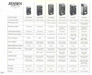
the speakers are jensen system 500
The speakers Box volume is about 75 liter sealed
the mid Box vulume is about 1.5-2 liter
it used to be 4 way but i canceled the rear tweeter and made it 3 way
the mid and the front tweeter are original and they both 8 ohm
i replaced the original woofer with this 12" dayton because it got ruin
https://www.parts-express.com/dayton-audio-ds315-8-12-designer-series-woofer-speaker--295-434
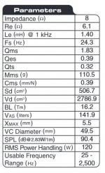
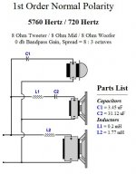
I replaced the original crossover with the crossover in the picture
C1 = 3.3 u
C2 = 30 u
L1 = 0.2 mH
L2 = 1.8 mH
Unpolorized electrolit capacitors I can buy
But inductors i can't buy beacuse it is too expensive
the tweeter power i would like to remain it as is
but the mid I think I should lower it
and off course i would like to give more power to the woofer
You got an idea what changes i should do ? thank you very much I am appreciate your help
The speakers Box volume is about 75 liter sealed
the mid Box vulume is about 1.5-2 liter
it used to be 4 way but i canceled the rear tweeter and made it 3 way
the mid and the front tweeter are original and they both 8 ohm
i replaced the original woofer with this 12" dayton because it got ruin
https://www.parts-express.com/dayton-audio-ds315-8-12-designer-series-woofer-speaker--295-434
I replaced the original crossover with the crossover in the picture
C1 = 3.3 u
C2 = 30 u
L1 = 0.2 mH
L2 = 1.8 mH
Unpolorized electrolit capacitors I can buy
But inductors i can't buy beacuse it is too expensive
the tweeter power i would like to remain it as is
but the mid I think I should lower it
and off course i would like to give more power to the woofer
You got an idea what changes i should do ? thank you very much I am appreciate your help
Attachments
I do not normally respond to threads. Choosing instead to read, and / or ask simple questions. At the end of this you'll see why I stay away.
The authors question is one which has been asked a thousand times. How do I improve the base?.
You all dance around with your answers, seemingly trying to keep threads alive. You do the newby DIY'er a great disservice.
Will someone please agree with me, 'the easiest way to improve the base of an existing design, is to improve the primary woofer inductor'.
WhiteRhino, don't be a cheapskate. Order a low rDC, baked impregnated iron cored inductor. No air core inductor should be used for woofer service. End of story.
The Mundorf BT140 line has rDC of 0.14 Ohms for the 1.8mH. I think you can get a pair for under $100
Please feel free to shoot me down.
thats ok Cousin Billy
The woofer inductor is Madisound Air Core Inductors 19 AWG 1.75mh which is 0.80 ohm DC resistance
Madisound Air Core Inductors 19 AWG: The Madisound Speaker Store
thats an good idea for low RDC inductor
(sorry I didn't thought about it at the first place )
but I looking for a cheap and simple solution
may be all I have to do is to put a resistor in front the mid and the tweeter as jReave mention ?
In principle you can not enhance the woofer, you have what you have.
If you have a bad cabinet you may improve it, but it does not seem to be the case.
So options are electronic:
1) if your cabinet sounds good but is bass shy, meaning the woofer has lower efficiency than mid and tweeter and you want to equalize that, you can attenuate them to lower their efficiency in line with the woofer's.
2) or you can electronically boost bass, with a tone control or a fixed bass boost circuit.
If you want to keep it real simple, cheap, etc. you attenuate mids/highs before the amp with 2 resistors and 1 capacitor per channel , conceptually the same as doing it at the crossover, but 1000000 times better for multiple reasons.
All for less than $5 in parts, ans infinitely more tweakable, which is not the case working at the crossover level.
FWIW, Parts Express itself recommends something like that:
Generous Xmax capability encourages use of moderate bass boost to tailor the response
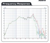
Rotten advice so far, IMO. Indiscriminately changing the woofer has actually taken you into a new world of pain! 
You see a woofer that will behave well on a mere 1.8mH coil is an unusual beast, probably with considerable mechanical damping. Is it Plastic? Certainly the replacement you have chosen is unsuitable for a mere first order crossover.
https://www.parts-express.com/dayton-audio-ds315-8-12-designer-series-woofer-speaker--295-434
That's a reflex driver that will also need a second order bass filter to cross around 700Hz. You might get away with closed box here, but it's not optimal. But mainly, this peaky replacement just won't work without a second order filter. 3.3mH series, 3.3R and 68uF shunt in my estimation. Then fiddle about with attenuators on mid and tweeter.
SEAS Kit 503
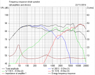
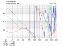
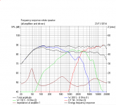
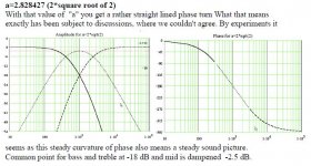
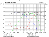
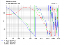
I have attempted to guess how your speaker works below. The bass gets a target response, and quite what happens with the upper midrange depends on the mechanical rolloff of the mid. Phase is rather good. But steeper, higher order filtering would work better. Or polycones.
You see a woofer that will behave well on a mere 1.8mH coil is an unusual beast, probably with considerable mechanical damping. Is it Plastic? Certainly the replacement you have chosen is unsuitable for a mere first order crossover.
https://www.parts-express.com/dayton-audio-ds315-8-12-designer-series-woofer-speaker--295-434
That's a reflex driver that will also need a second order bass filter to cross around 700Hz. You might get away with closed box here, but it's not optimal. But mainly, this peaky replacement just won't work without a second order filter. 3.3mH series, 3.3R and 68uF shunt in my estimation. Then fiddle about with attenuators on mid and tweeter.
SEAS Kit 503
I have attempted to guess how your speaker works below. The bass gets a target response, and quite what happens with the upper midrange depends on the mechanical rolloff of the mid. Phase is rather good. But steeper, higher order filtering would work better. Or polycones.
Attachments
-
 Dayton Designer Series 12 inch woofer FResp.JPG41.8 KB · Views: 203
 -
 Dayton Designer Series 12 inch woofer Parameters.JPG48.6 KB · Views: 168
 -
 Jensen System 500 Crossover.PNG8.2 KB · Views: 166
 -
 Jensen System 500 Freq Resp Estimate.PNG14.3 KB · Views: 166
 -
 Jensen System 500 Phase.PNG27.5 KB · Views: 52
I can do it in pre amp because i have an opamp preamp , thanks .If you want to keep it real simple, cheap, etc. you attenuate mids/highs before the amp with 2 resistors and 1 capacitor per channel , conceptually the same as doing it at the crossover, but 1000000 times better for multiple reasons.
i will try it .
may be i can stay with the 1.75mH inductor and do like thisThat's a reflex driver that will also need a second order bass filter to cross around 700Hz. You might get away with closed box here, but it's not optimal. But mainly, this peaky replacement just won't work without a second order filter. 3.3mH series, 3.3R and 68uF shunt in my estimation. Then fiddle about with attenuators on mid and tweeter.
Attachments
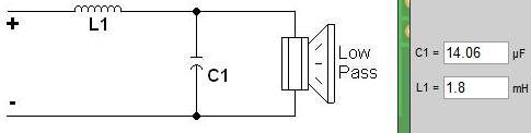
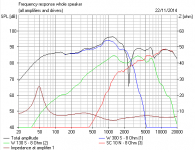
I don't know what you are using to model the bass, but it's NO GOOD.
To hit a 700Hz crossover, you need a lot more. Your 1.8mH and 14uF bass filter will end you up roughly below. That's useless. Takes no account of driver inductance and mechanical rolloff and bafflestep, you see.
Downloads
http://boxsim-db.de/lotte/
This "Lotte" project can be imported into the "Projekte" folder for a quick start. Then change the drivers to a W130S mid in a 10L enclosure. And a SC10N tweeter. You'll probably need to make the box bigger for a 12 " driver like the W300S. After that, you select components in red and "optimise". You might have to flip polarity to get phase aligned. Very cool.
Attachments
Last edited:
this is the crossover right now ignore what i says before i had a mistake .
C1 = 3.3 u
C2 = 31 u
L1 = 0.2 mH 0.17 Ohm RDC 19AWG AIR COIL (plastic )
L2 = 1.75 mH 0.8 Ohm RDC 19AWG AIR COIL ( plastic)
the is woofer
https://www.parts-express.com/dayto...9111X1517312Xbe002a7f99e102bd6c36c5d208393621
don't you have any suggestion to make a good crossover and stay with this inductors ?
if the LPF will go to 1000 HZ that's no big deal just the bass response will be good .
Attachments
I have no idea if this will sound any good, but there is a way of applying a passive sort of bafflestep correction. It tends to make for an easy load.
It's really not a question of 10% here and there, it's the choice of replacement woofer and a simplistic crossover that is giving you grief. Really, my friend, you should study that link I gave you. I can't give you 40 years of experience in 5 minutes.
SEAS Kit 503
It's really not a question of 10% here and there, it's the choice of replacement woofer and a simplistic crossover that is giving you grief. Really, my friend, you should study that link I gave you. I can't give you 40 years of experience in 5 minutes.
SEAS Kit 503
Attachments
Rhino, here's the deal - to properly design a speaker xo I need to have the TS parameters, the FR and the impedance for each driver. We have these for the DS315-8 but not for your mid and tweeter. That means all we can do is sort of shoot in the dark with a trial and error approach.
Graph 1: DS315-8 (not some other driver) on a 15.25"x29" baffle, no edge treatment, in about 55L (gross volume for your cabinet dimensions is 61L assuming 3/4" walls), centered 8" above the bottom with a 1.8mH (.8ohm) inductor with 4dB of baffle step loss included. This is why you lack bass - you have not compensated for the baffle step loss.
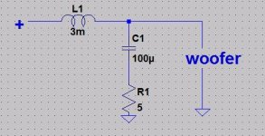
Graph 2: Baffle step loss compensated for with 3mH in series and 100uF + 5ohm in parallel. The resonance peak at 2kHz is now down about 12dB, so only about half as loud as currently.
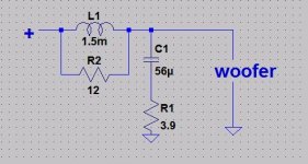
Graph 3: system7's suggested 1.5mH + 12ohm bsc circuit plus the 56uF and 3.9ohm in parallel. Much better than graph 1 but not quite as good as #2.
Since money is a consideration for you, let me ask if you happen to still have the old xo parts for your speaker, especially the old inductors for the woofers still sitting around? Inside the speaker by any chance?
If not, you really are going to need to buy some new parts. Electrolytic caps and resistors are cheap and you don't really need big inductors (you could add something like 1.2 to your 1.8 to get a 3mH value). The problem though is that we really don't know what the FR of your mid is in reality so you're just going to have to try some different things, like more resistance on the tweeter and mid and perhaps a bigger value on C2, to see what happens.
Of course, if you want to do the absolute easiest thing to increase the response below about 100Hz, put them on the floor in the corners.
Graph 1: DS315-8 (not some other driver) on a 15.25"x29" baffle, no edge treatment, in about 55L (gross volume for your cabinet dimensions is 61L assuming 3/4" walls), centered 8" above the bottom with a 1.8mH (.8ohm) inductor with 4dB of baffle step loss included. This is why you lack bass - you have not compensated for the baffle step loss.
Graph 2: Baffle step loss compensated for with 3mH in series and 100uF + 5ohm in parallel. The resonance peak at 2kHz is now down about 12dB, so only about half as loud as currently.
Graph 3: system7's suggested 1.5mH + 12ohm bsc circuit plus the 56uF and 3.9ohm in parallel. Much better than graph 1 but not quite as good as #2.
Since money is a consideration for you, let me ask if you happen to still have the old xo parts for your speaker, especially the old inductors for the woofers still sitting around? Inside the speaker by any chance?
If not, you really are going to need to buy some new parts. Electrolytic caps and resistors are cheap and you don't really need big inductors (you could add something like 1.2 to your 1.8 to get a 3mH value). The problem though is that we really don't know what the FR of your mid is in reality so you're just going to have to try some different things, like more resistance on the tweeter and mid and perhaps a bigger value on C2, to see what happens.
Of course, if you want to do the absolute easiest thing to increase the response below about 100Hz, put them on the floor in the corners.
Attachments
could you draw me the circuit so I will be sure ?Graph 1: DS315-8 (not some other driver) on a 15.25"x29" baffle, no edge treatment, in about 55L (gross volume for your cabinet dimensions is 61L assuming 3/4" walls), centered 8" above the bottom with a 1.8mH (.8ohm) inductor with 4dB of baffle step loss included. This is why you lack bass - you have not compensated for the baffle step loss.
Graph 2: Baffle step loss compensated for with 3mH in series and 100uF + 5ohm in parallel. The resonance peak at 2kHz is now down about 12dB, so only about half as loud as currently.
Graph 3: system7's suggested 1.5mH + 12ohm bsc circuit plus the 56uF and 3.9ohm in parallel. Much better than graph 1 but not quite as good as #2.
T.S.Eliot said:“Between the conception and the creation,
Between the emotion and the response,
Falls the Shadow”
Here's a three way modelled AND OPTIMISED on a 80cm by 36cm baffle in Boxsim.
This follows Steen Duelund's ideas. You can eliminate the small capacitors and inductances to allow for real world driver responses.
Very advanced stuff here, but it's the reality.
Attachments
Last edited:
I am very appreciate your help guys and I am sorry I did not under stand you well
I am looking for a cheap solution , i can buy capacitors and resistors with no problem , but inductors i can buy only two for LPF and no more .
if you have an idea how to do it with this budget I will be glad
I saw in ebay this crossover do you think it will be good ?
2pcs New for Kasun as 33c 3 Way 3 Unit Hi Fi Speaker Frequency Divider Crossover | eBay
Attachments
No, stay away from those prefab xo's. They'll probably just create more problems than you already have so far.
Ok, here's what we know. The original xo was 1st order at 760Hz. I'm going to guess therefore that the original woofer inductor is probably close to what you are using now, 1.8mH plus or minus.
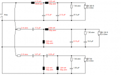
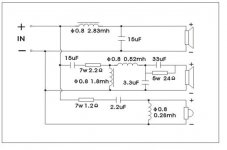
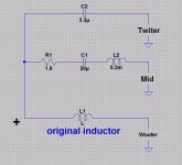
So, what you want to do is connect both inductors together in series for a value of (hopefully) something between 3 and 4mH. But you'll also need to add a capacitor and resistor in parallel so that you compensate for baffle step loss and get a decently flat response from the woofer and thereby add more bass to the speaker.
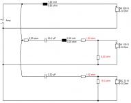
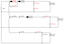
Below, 1st chart is the correct topology.
Second chart shows you a 760Hz 1st order target slope in red and then the blue response is the woofer response with 3.8mH in series and 30uF + 15ohm in parallel.
However, I'm guessing on the inductor value. Maybe it's lower, in which case you need to increase the value of C1 (try increments of 10-20uF) and decrease R1 (try increments of 1ohm) to maintain the same response. The 3rd chart is with L1 = 3mH, C1 = 80uF and R1 = 10ohm. Pretty much exactly the same response as the 2nd chart.
The last chart shows you how to get rid of that 2.2kHz peak by adding a simple 1.4uF capacitor in parallel with L1. Perhaps try it without at first and then if you notice that the resonance bothers you, try adding it in.
As you do this, you'll also have to add resistance to the mid and tweeter to get a proper balance with the new woofer response. So lots of try something, see how it sounds and then repeat as necessary. It will help therefore if you can figure out how to get the xo's out of the box while you make the changes and listen to the results.
Let me know if I've written this up clearly enough so that you understand everything. If you have the old xo capacitors, you can use those. Otherwise, you'll need to buy something like 30uF and/or 5 or 6 x10uF for each speaker. For resistors, maybe 10ohm plus 8 or 10 x 1ohm. I'm hoping btw that you know how capacitors add up in parallel and how resistors add up in series.
Ok, here's what we know. The original xo was 1st order at 760Hz. I'm going to guess therefore that the original woofer inductor is probably close to what you are using now, 1.8mH plus or minus.
So, what you want to do is connect both inductors together in series for a value of (hopefully) something between 3 and 4mH. But you'll also need to add a capacitor and resistor in parallel so that you compensate for baffle step loss and get a decently flat response from the woofer and thereby add more bass to the speaker.
Below, 1st chart is the correct topology.
Second chart shows you a 760Hz 1st order target slope in red and then the blue response is the woofer response with 3.8mH in series and 30uF + 15ohm in parallel.
However, I'm guessing on the inductor value. Maybe it's lower, in which case you need to increase the value of C1 (try increments of 10-20uF) and decrease R1 (try increments of 1ohm) to maintain the same response. The 3rd chart is with L1 = 3mH, C1 = 80uF and R1 = 10ohm. Pretty much exactly the same response as the 2nd chart.
The last chart shows you how to get rid of that 2.2kHz peak by adding a simple 1.4uF capacitor in parallel with L1. Perhaps try it without at first and then if you notice that the resonance bothers you, try adding it in.
As you do this, you'll also have to add resistance to the mid and tweeter to get a proper balance with the new woofer response. So lots of try something, see how it sounds and then repeat as necessary. It will help therefore if you can figure out how to get the xo's out of the box while you make the changes and listen to the results.
Let me know if I've written this up clearly enough so that you understand everything. If you have the old xo capacitors, you can use those. Otherwise, you'll need to buy something like 30uF and/or 5 or 6 x10uF for each speaker. For resistors, maybe 10ohm plus 8 or 10 x 1ohm. I'm hoping btw that you know how capacitors add up in parallel and how resistors add up in series.
Attachments

I think you're quite right, jReave, that 2kHz cone breakup peak needs treatment.
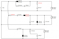
I was further playing with this circuit in Boxsim, and the notch works well. I also tried to reuse the 30uF and 1.8mH. The modelling says third order tweeter, but hey, we're trying to keep costs down. Here in the UK, ferrite coils cost around £5 a pop. http://www.wilmslow-audio.co.uk/bits--pieces-16-c.asp
I think electrolytics will be fine in most places too, except for the 1uF notch and 4.7uF tweeter.
I can't advocate simplifying the mid crossover further, because that will let in too much 6kHz cone breakup from the mid. I think this looks nice enough to build and tweak for level if necessary.
Attachments
- Status
- This old topic is closed. If you want to reopen this topic, contact a moderator using the "Report Post" button.
- Home
- Loudspeakers
- Multi-Way
- A liltle modification to a cross over to boost the woofer