K means kiloohms
no wonder that you don't have current there
so , buy 27K , or 27.4K , and you're good
Dennis made a mistake (linking to 27.4R instead to 27.4K) , but that's normal (it happens) .... we are all used that schematic must be understood , at least on parts values and designation level
it is clearly written on all schematics that's kiloohm range resistor
Last edited:
OK, just to double check before ordering?
RN60D2742FB14 Vishay / Dale | Mouser France
RN60D2742FB14 Vishay / Dale | Mouser France
")
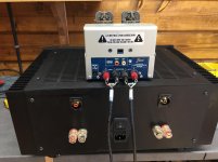
Fantastic, my F4 is now up and running. I could not have completed this project without all the help from experienced builders: a big thank you to 6L6 for the guide, CAL for the BOM and all the people who have helped me to better understand the process and troubleshoot my problems. Jeff, Zen, 6L6, Syracuse and of course Dennis who has frequently replied faster than members of my own family get back to me.
Starting with the ACA build was an excellent first step. Having now finished my F4, I feel a little higher up the ladder (perhaps from incompetent to mildly capable). I'm hoping to build other things in the future and will take everything I have learnt here into those projects. Thanks also to Nelson for sharing his designs with the DIY community, extremely generous.
Starting with the ACA build was an excellent first step. Having now finished my F4, I feel a little higher up the ladder (perhaps from incompetent to mildly capable). I'm hoping to build other things in the future and will take everything I have learnt here into those projects. Thanks also to Nelson for sharing his designs with the DIY community, extremely generous.
Attachments


Hi Dennis,
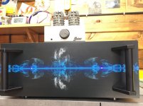
The front plate was done at HIFI 2000, I simply supplied the image which must be at least 4K and Gianluca centred it onto the plate. I prefer it to a plain front and it's a lot cheaper than loads of engraving and fancy stuff.
Hi Zen,
Don't you mean Foutiful!!
The front plate was done at HIFI 2000, I simply supplied the image which must be at least 4K and Gianluca centred it onto the plate. I prefer it to a plain front and it's a lot cheaper than loads of engraving and fancy stuff.
Hi Zen,
Don't you mean Foutiful!!
Last edited:
The Elekit was a mild concern before I started as it is only 2W, no problems at all it goes way louder than I am able to withstand.
Yes, because it’s ability to swing voltage into the speakers wasn’t it’s issue, but that it had no current capability, being a small valve SE amplifier.
Now that it’s freed from having to move current into a speaker load, and only needs to make voltage swing, it’s off to the races and wonderfulness!
Hi, everyone! I've dithered in the past about building the F4 or Aleph J, but now I'm finally going to do it. I have F4 boards and the store is out of Aleph J boards, so that makes the way forward simpler. I asked earlier about whether my current system will have enough voltage swing to drive my speakers adequately. The consensus was . . . maybe. So I'll see how it goes with the preamp feeding the F4.
In case, the preamp doesn't cut it, and I need to use my 1-watt OTL preamp/amp (LTA MZ2) to drive the F4, how do I implement what Nelson said in the manual? "In this arrangement you can also load the flea watt amp (not shown here) with a resistive or other load which elicits the best performance from it." Does this mean attaching a 5W (or so) resistor at the source amp's speaker output(s) when feeding the output signal to the F4's input? If so, just one resistor on the positive or negative terminal of each channel, or both terminals? Perhaps a value of 6 ohms (nominal value of my Omegas)? I imagine putting a pot there and experimenting with different values before selecting a fixed resistor might prove useful.
Damn it, I just noticed 66deg's picture of the resistors across the outputs. Wow, that's embarrassing.
Last edited:
Food for thought. Usually the higher wattage the resistor the cooler it will operate at. If you are going to always use the tube amp, why not install the burden resistor inside the chassis, on the RCA jacks? If you’re feeling fancy you could even add a switching means to remove the resistor form the circuit.
Fantastic, my F4 is now up and running....
Starting with the ACA build was an excellent first step. Having now finished my F4...
Gorgeous amp!
You took the same route as I am underway (ACA – 2 pitstops with a DCB1 and a bugle2 – on to the F4, so may I ask...
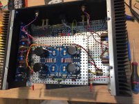
Is this a 4U chassis?
Why did you elevate the PSU-Unit, is the toroid underneath? (Ain‘t this a problem?)
What did you populate the PSU-Board with?
Thanks! Happy listening!
David
- Home
- Amplifiers
- Pass Labs
- A guide to building the Pass F4 amplifier