Another data point for a 230V country:
I use just one 1 CL-60 in total for 2 strings of each 400VA, 132mF - 2x 1.5 mH - 132mF - 2x 60 uF motor run. (dual mono PSUs).
Separate fuse for each toroid. Plus one „master fuse“ up front in the IEC socket, that one 1.25A.
No problem with just one CL-60.
This is for my SissySIT; steady-state power draw from the wall up to 235W.
Regards, Claas
In steady state (after inrush) the amp draws twice as much current from 115V mains, as it draws from 230V mains. So it makes sense to have half as much resistance in series with 115V mains, than you have in series with 230V mains.
Nelson Pass's idea of one Inrush Current Limiter "CL60" for the 230V case, and two CL60s for the 115V case, seems to me quite sensible.
Nelson Pass's idea of one Inrush Current Limiter "CL60" for the 230V case, and two CL60s for the 115V case, seems to me quite sensible.
Hello All,
Just bought the hardware for the F4 from DIY Audio and it's in transit. While waiting for it to arrive I’m wading through the incredibly helpful F4 and PSU build guide threads and associated posts and finding suppliers for the parts I need. I can’t find any quality components here in Belarus so have to import everything (+30% tax)! I’ve nearly completed my BOM and I’m hoping someone can help me on one component that I haven’t found an answer to yet:
1. Panasonic 0.47 ohm 3 watt MOX resistors. Mouser in Russia are o/s and give an eta of 18 weeks. I had hoped to have the amp up and running by then at the latest! Can anyone give me a common replacement for the Panasonic please? I can get Jantzen or Mundorf 5w MOX easily but they are much larger (24mm l x 8mm dia) and I don't think they will fit in some locations - I maybe wrong as I don’t have the pcbs yet so any clarification about that would also be appreciated.
2. Can anybody tell me what diameter the holes for the components are on the F4 and PSU pcbs or what the max size of the wire that can be used. I have plenty of high quality ‘speaker wire’ at 2.1mm dia (12AWG) and wondered if that would fit the holes in the pcb or whether I need to buy something smaller.
Thanks
I just tried measuring a board and the resistor holes are 20mm apart.
Is the Dale CPF3R47000JNB14 available at your mouser location?
CPF3R47000JNB14 Vishay / Dale | Mouser Canada
The holes for V+, V-, IN, OUT and GND appear to be about 2mm on the F4 board. I only have
a ruler so I cannot be more accurate. Unfortunately I don't have any 12 AWG
wires to try. I'm guessing it might work (and fit snugly).
Hope this helps.
Dennis

sole wire through hole - better to avoid
whenever you need to put wire through hole , make it with natural pair - lead and return
though , ppl are saying that same thing is with output binding posts
anyway, better err on safe side")
also - those eyelets on mains wires (terminal block on bottom plate) ....... they're so better looking when heatshrinked
whenever you need to put wire through hole , make it with natural pair - lead and return
though , ppl are saying that same thing is with output binding posts
anyway, better err on safe side
also - those eyelets on mains wires (terminal block on bottom plate) ....... they're so better looking when heatshrinked
Last edited:
I'm building the F4 and already bought Infineon IRFP9140 mosfets and matched them. Anyone know if the transconductance vs frequency shelving issue in the IRFP9240 happens in other mosfets, such as the IRFP9140 by Infineon? I wasn't too worried about it, but it came up in conversations with another DIYer.
Thanks,
Vince
Thanks,
Vince
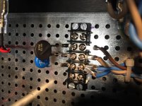
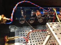
At the moment switch on results in two blown fuses, I must have connected something incorrectly.
The Middle wire on the CL60 connection is from the IEC, I'm fairly sure this is correct and the wires from the transformer are two yellows on the left which were labelled 1&2 and two reds on the right which were labelled in the same way. If that is correct then does anyone have any suggestions as to where I have gone wrong?
The Middle wire on the CL60 connection is from the IEC, I'm fairly sure this is correct and the wires from the transformer are two yellows on the left which were labelled 1&2 and two reds on the right which were labelled in the same way. If that is correct then does anyone have any suggestions as to where I have gone wrong?
Attachments

No sorry, I don't have a datasheet for xformer.
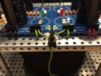
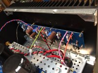
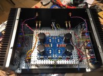
The transformer has a rubber plate underneath which has one central bolt through the middle, this is in contact with the metal base plate, this and the primary and secondary wire are the only connections for the transformer.
I have checked for continuity on the secondary wires, which is one yellow to one red.
Is this the datasheet required.Power rating: 756VA
Primary: 0-230V @ 50Hz
Secondaries: 2 x 0-18V @ 21A rms
Regulation: approx 5%
Estimated dimensions: 163mm diameter away from leadouts x 82mm high
Mounting: standard mounting kit (adds approx 4.5mm to the height)
Leadouts : approx 200mm long flexible (stranded)
Audio grade construction
Primary: 0-230V @ 50Hz
Secondaries: 2 x 0-18V @ 21A rms
Regulation: approx 5%
Estimated dimensions: 163mm diameter away from leadouts x 82mm high
Mounting: standard mounting kit (adds approx 4.5mm to the height)
Leadouts : approx 200mm long flexible (stranded)
Audio grade construction
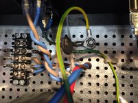
I have checked for continuity on the secondary wires, which is one yellow to one red.
Your picture shows two yellow wires to one bridge and two red wires to the other bridge. If continuity is yellow to red, then you need to connect a continuous pair to each bridge.
- Home
- Amplifiers
- Pass Labs
- A guide to building the Pass F4 amplifier