..... (I hate desoldering 3 pin
devices.)
.....
that's why you're having two soldering stations on your bench - one with smallish tip , for soldering all those little buggers and another one - with 6-7mm wide knife-like tip , for soldering fat wires (increased temperature inertia is important there) and desoldering 3 pins at once
melt all-pull out-clean pads one by one later
You guys are awesome! One down and one to go. I feel like a one man Pass "F4" pit crew with as many times as I've taken this amp apart and put it back together.
So, I took the PSU out, toroid out, "Channel 2" board out. Took out the 10k of the 22k1 + 10k pair at R8 and replaced 10k with 47k5.
Lookie Lookie Lookie... Woo Hoo.

Left is the voltage across the source resistor. Right is the voltage between the gates.
I wanted to get it up to 0V2 just to make sure that I did't run out of room later.
On to add 47k5 to Channel 1 R8.

So, I took the PSU out, toroid out, "Channel 2" board out. Took out the 10k of the 22k1 + 10k pair at R8 and replaced 10k with 47k5.
Lookie Lookie Lookie... Woo Hoo.
Left is the voltage across the source resistor. Right is the voltage between the gates.
I wanted to get it up to 0V2 just to make sure that I did't run out of room later.
On to add 47k5 to Channel 1 R8.
Another F4 is born with help from the family here! I let it cook for an hour at 0V250 and nulled the offset. Once the correct components are used  it is exceptionally simple and very responsive / sensitive to changes to dial it right in. I think b/c the Vgs of my N and P were relatively close, even when I altered the bias substantially, DC offset didn't budge very much from the initial nulling.
I listened for 10 mins or so on the test bench and felt comfortable enough to move it to the main rig. I don't have proper gear to test the distortion levels etc, but Jim mentioned his "sweet spot" was 0V300. I'll monitor temps, but I'm only at 44C on the heatsinks at 0V250. I'll judge by ear and whether I want it to warm me up. MN in the winters is chilly.
As always... My most sincere thanks to @Nelson Pass. I've embarked on a journey of learning and musical enjoyment that would not have been possible without your generosity. I hope to shake your hand in November.
I could never have done it without Jim's build guide. That's how I get started on all my builds.
I certainly never could have done it without the MIGHTY and very generous Zen Mod, Dennis, and Jeff. With a hats off to Dennis. I read and reread around post #694 to learn from the gentleman that had a very similar issue, but I still could not solve it on my own even with post #705 re: the specs for the different TI voltage regulators. Your collective knowledge and patience with noobs is both remarkable and heartwarming. Live and learn, learn, learn.
Time to jam!
it is exceptionally simple and very responsive / sensitive to changes to dial it right in. I think b/c the Vgs of my N and P were relatively close, even when I altered the bias substantially, DC offset didn't budge very much from the initial nulling.I listened for 10 mins or so on the test bench and felt comfortable enough to move it to the main rig. I don't have proper gear to test the distortion levels etc, but Jim mentioned his "sweet spot" was 0V300. I'll monitor temps, but I'm only at 44C on the heatsinks at 0V250. I'll judge by ear and whether I want it to warm me up. MN in the winters is chilly.
As always... My most sincere thanks to @Nelson Pass. I've embarked on a journey of learning and musical enjoyment that would not have been possible without your generosity. I hope to shake your hand in November.
I could never have done it without Jim's build guide. That's how I get started on all my builds.
I certainly never could have done it without the MIGHTY and very generous Zen Mod, Dennis, and Jeff. With a hats off to Dennis. I read and reread around post #694 to learn from the gentleman that had a very similar issue, but I still could not solve it on my own even with post #705 re: the specs for the different TI voltage regulators. Your collective knowledge and patience with noobs is both remarkable and heartwarming. Live and learn, learn, learn.
Time to jam!
Another F4 is born with help from the family here! I let it cook for an hour at 0V250 and nulled the offset. Once the correct components are used
I listened for 10 mins or so on the test bench and felt comfortable enough to move it to the main rig. I don't have proper gear to test the distortion levels etc, but Jim mentioned his "sweet spot" was 0V300. I'll monitor temps, but I'm only at 44C on the heatsinks at 0V250. I'll judge by ear and whether I want it to warm me up. MN in the winters is chilly.
As always... My most sincere thanks to @Nelson Pass. I've embarked on a journey of learning and musical enjoyment that would not have been possible without your generosity. I hope to shake your hand in November.
I could never have done it without Jim's build guide. That's how I get started on all my builds.
I certainly never could have done it without the MIGHTY and very generous Zen Mod, Dennis, and Jeff. With a hats off to Dennis. I read and reread around post #694 to learn from the gentleman that had a very similar issue, but I still could not solve it on my own even with post #705 re: the specs for the different TI voltage regulators. Your collective knowledge and patience with noobs is both remarkable and heartwarming. Live and learn, learn, learn.
Time to jam!
Congrats! It's a great amp. Hope you love it!
Congrats! It's a great amp. Hope you love it!
Thank you very much!
My speakers are pretty efficient (98dB @ 2.83V/1m) 4Ohm nominal. My primary preamp has 20dB of gain and will provide 10V with the current set up. I can easily see me investing in another set of F4 boards and doing mono blocks. Being able to get the full 20V swing from my pre-amp with a balanced configuration would be ideal. I've also never tried monoblocks. It could be a great learning experience.
It sounds exceptionally good to my ears (as does every First Watt design I've tried).
Edited to add - I hit submit too soon. I also have really been looking forward to pairing it with a few tube amps. That will come later. There's still a lot I need to learn before doing that. I read the posts earlier in the thread, but some of it went over my head re: selecting the proper resistance to use.
Last edited:
I also built the full mono-blocks, but didn't find it necessary for my speakers (Coincident Pure Reference Extremes; Impedance: 8 ohms - never dipping below 6 or going above 10 ohms, Sensitivity: 94 db @ 1M - 1 watt).
I first tried vertical biamping my speaker's passive subwoofer units & the head-units (both require their own speaker connections). That hurt coherency pretty significantly. Eventually moved to paralleled inputs and outputs to double current, but that didn't provide any real benefit, and I think introduced a bit of smearing to the sound. Tough to say how much difference there really was, but I clearly didn't need the power and ended up just running them in a standard dual mono block build... a single channel in each chassis with its own power supply. I think if you don't need the power, then that's the way to go. An added plus is that you can put a different board in the other half and just switch amps when you feel like playing with a different flavor.
If you haven't already, I'd check and see how much power your speakers pull at max volume... A Test. How much Voltage (power) do your speakers need?
simple as -
you need more power on lower (ohmic) load - parallel (SE connection)
you need more power on higher (ohmic) load - bridge (BAL connection)
to paraphrase my self :
Don't use Force - use more efficient speakers
for BAL connection, 8 ohm 100watt, and lesser on 4 ohm. am i right?
I have a question regarding switching off the power of f4 between the power supply and the f4 boards themselves.
I am building integrated amp - BA3 front end plus F4. But I want to have possibility to switch off the f4 keeping the input stage on. In that case it can serve as a preamp for example to drive a headphones with some buffer after it.
The obvious way is to put some kind of switch between the power supply board and the f4 boards. But Is this good idea?
How will f4 behave when the voltage of already switched on supply is suddenly switched on?


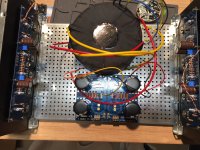
I have also done an unsoldered power supply board and have a few questions.
1) R1 to R8 are all 0.47 ohms 3W 5% but not the big blue ones, are they different in some way?
2)R20 , R21 I can't seem to find a value for these resistors, RN 60 4752f is one of the things leftover (so I put them in for the photo) but I also have some 1K ohms 1/4 w 1% leftover as well, Is either one of these OK or should I order something else.
3) R9, R10 bleeder resistor I think is OK but will simply drain a little slower?
4)My LEDs are positioned cathode - towards the middle, which has a continuation to the ground so fairly sure that is OK.
5) Lastly, my large caps are 18000uf 50V which aren't the same as in the build guide so just wanted to check that as well?
Before starting this F4 build I made some slate and oak Pensil speakers, Stefan over at KJF Audio asked me to do a build guide for his website. He has just put it up yesterday and I am posting a link here on DIY Audio. ( My little contribution to a great community).
Oak and Slate Pensil 12 build by Simon Sterritt | KJF Audio
Oak and Slate Pensil 12 build by Simon Sterritt | KJF Audio
Last edited:
Assuming you're using this schematics: https://cdn.shopify.com/s/files/1/1006/5046/files/P-PSU-1V30-schematic.pdf
1) Those Vishay resistors are fine.
2) Your 4752 resistor is 47.5K. Assuming your rail voltage ~25V and LED drop around 3 volts, you get about 0.5mA through the LED. Might be enough to turn on LED.
If you find it dim, decrease the resistor value. 1k may be too bright.
3) 22K for bleeder will drain quite slowly but otherwise ok.
4) On the + rail, the LED cathode goes to ground, while on the - rail, the LED
anode goes to ground. You can see that in the schematics.
5) Caps are fine.
My transformer is quite large which is causing some space issues, is it OK to split the power supply board down the middle. There seem to be no connections in the traces on the boards and I think I would just need to take a wire across on order to connect the two GND.
Attachments
- Home
- Amplifiers
- Pass Labs
- A guide to building the Pass F4 amplifier