Sir Apex here is my on going projects...thanks and regards.
Nice work
Regards
Mr Mile do you have PCB for these preamplifiers?
No coupling caps at in/outputs with the BJT version. Don't connect this one to a DC coupled power amp.
No GND reference resistors with the FET version so large plops when connecting it to a power amp. Schematics seem to be that of prototype versions.
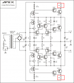
BJT Preamplifier - A Class PSU
Hello Mr Miles!
I plan to make your preamplifier with your "A class PSU" but I have a few questions before I start.
- The version of the preamplifier (bjt) it can be supplied with +-15V?
- This preamplifier can it be preceded by your (bjt) buffer or is it stupid?
Thank you and friendly!")
Hello Mr Miles!
I plan to make your preamplifier with your "A class PSU" but I have a few questions before I start.
- The version of the preamplifier (bjt) it can be supplied with +-15V?
- This preamplifier can it be preceded by your (bjt) buffer or is it stupid?
Thank you and friendly!
Hello Mr. Miles!
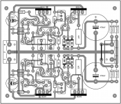
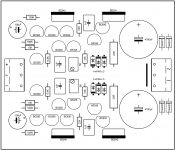
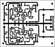
I draw a circuit to supply this and here are some images.
When my realization is complete and if everything is ok I will move my version of the circuit in pdf format.
Thank you and friendly!
I draw a circuit to supply this and here are some images.
When my realization is complete and if everything is ok I will move my version of the circuit in pdf format.
Thank you and friendly!
Attachments
Hello Mr. Miles!
I draw a circuit to supply this and here are some images.
When my realization is complete and if everything is ok I will move my version of the circuit in pdf format.
Thank you and friendly!
Nice work,
Regards
VR 1k must be replaced with 4k7 for BF245A, and regulation output voltage will be from +/12V to +/-24V.
Apex
I found BD245B. Anything I need to change or is this okay for the psu?
Hello Mr. Miles
A small question!
For resistors 22R (BD241 - BD242 collector) It takes 1W or 1/2W may agree?
Thank you!
1/2W will be ok
Hello Miles!
My circuit is completed and I will now turn to my sharing of components.
In my local store the BC639 & BC640 are not available and I thought up instead of BC327 & BC337.
The BC639 & 640 have an IC 1A.
The BC327 & 337 have an IC 800mA.
I can use?
For BD241 & 242 My local store has TIP41 & TIP42 I think surdimentionnement no problem.
Thank you!
Hello Miles!
I found BC639 & BC640!
My power supply works but the adjustable resistors have no effect.
For testing I connected transformer 2x14v and I have + / - 18v output. Another transformer 2x17v and I have about + / - 24v output but no ability to adjust the output voltage.
I checked my circuit several times and everything seems ok.
I am doing test without adjustable resistors and output I + / - 0v.
Any idea?
Attachments
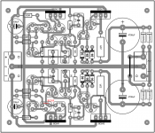
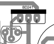
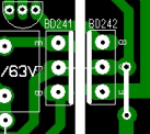
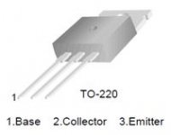
I can't read the lower drawing clearly.
But it looks like the bd242 has been reversed to fit the heatsink, but the pin labels have been left in the non reversed places.
The BD241 is definitely wrong.
The Pins are labeled ECB, but all To220 are BCE.
The top left drawing and the top right drawing are correct for To220, BCE.
But it looks like the bd242 has been reversed to fit the heatsink, but the pin labels have been left in the non reversed places.
The BD241 is definitely wrong.
The Pins are labeled ECB, but all To220 are BCE.
The top left drawing and the top right drawing are correct for To220, BCE.
Hello everyone!
I needed a single-rail PSU +24v, so I used an apex schematic but modified it in a way, that I took only above part (positive) and feeded it from a ready rectifier. So I have on input about 36v dc (24/1,4) but whatever I do, i have on output no more then 13v.
I couldn't get BD241/2 so I replaced them with MJE3055/29T. Can that be a problem?
Or I suspect that 15K is too much for BF245 in this case and this value should be different for a single-rail PSU. Any ideas?
To AndrewT
Hello! I deeply appreciate your answer. But there is some confusing. I red again your post and you were talking about Vac, but originally I was stating 13v vdc on output.
So I am feeding circuit from a bridge rectifier. Since I do not need a bipolar PSU
25V ac gives 36,7 dc. Minus goes to ground and plus
to circuit. On output I have only 13V of vdc with load
and (36!) with no load, so there is a huge voltage drop.
AC ripple is about 10mv, what is already pretty good comparing to IC regulators. That's why I am bothering with this circuit. Can you kindly enlight me? Do you know any reference voltages?
- Home
- Amplifiers
- Power Supplies
- A-class Preamp PSU