Hi all,
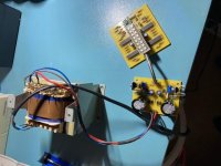
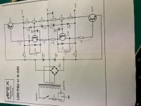
The assembly is the following: mains transformer 220 / 2x24Vac - stabilizer - the load that is powered at 2x15Vdc with a maximum consumption of 100-150mA.
The phenomenon is:
1 - when the assembly is powered by the network, all this work does not work, the voltage on the positive branch + 15Vdc and 0Vdc decreases somewhere up to 5Vdc and the value between 0Vdc and -15Vdc remains ok in the parameters.
2 - if I interrupt the power supply between the stabilizer and the load for an interval of 1-2 seconds everything works properly.
What is this phenomenon called, what is its cause and what is the remedy?
Please confirm you talk about the schematic in post 269
https://www.diyaudio.com/forums/power-supplies/164365-class-preamp-psu-27.html#post6169207.
Do I understand you correctly that the negative output is
fine and the positive drops with load ? In # 279 you wrote
it can be adjusted properly.
Check input voltages at rectifier under load also.
https://www.diyaudio.com/forums/power-supplies/164365-class-preamp-psu-27.html#post6169207.
Do I understand you correctly that the negative output is
fine and the positive drops with load ? In # 279 you wrote
it can be adjusted properly.
Check input voltages at rectifier under load also.
Re your point 2 - this may be called latch up.
Did you try to power on with power switch ?
I wrote check input voltages also, these are missing from the figure.
Seems like a start up problem. Try to decrease 4k7 base resistor BD 140.
I put R of 3K9 same result
I put R of 3k6 the problem moved on the negative branch only the output voltage is -0.7v ...
Yes, but this is for up to 24 volts output. Exactly the voltage
I asked for was missing in your drawing. Why would I ask ?
For your need the input voltage is too high, a waste of power
and pass transistors will heat up.
Check your board, especially all connections to "ground".
I asked for was missing in your drawing. Why would I ask ?
For your need the input voltage is too high, a waste of power
and pass transistors will heat up.
Check your board, especially all connections to "ground".
Yes. I have a power switch, the same result. I think it's about the consumption of the assembly ...
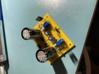
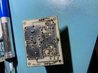
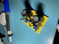
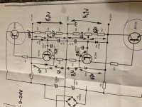
I made measurements and wrote on the diagram, you can see in the picture.
Replace BC546 and 6v8 zener... there must be some mistake on your pcb.
Hi,
I managed to solve the problem with the help of a colleague.
After verifications we came to the conclusion that one of the branches did not synchronize perfectly with the other, that's why the BD140 transistor did not open and the source remained blocked on the '' + '' branch. A negative voltage of about ''-7Vdc'' appeared on this branch.
To prevent this from happening again, I added a 470nF capacitor between the collector and the emitter of transistors BC546 and BC556.
Now everything works perfectly.
Thanks for the help.
Attachments
Im confused. Pls forgive this noob. So all this is about a power supply for a pre-amp. X Voltage Y mili amps.
Why is it so complex ?. Whats wrong in using a LM78xx/79xx regulator or even a simple circuit with a zener diode of desired voltage and resistor. Or if you want a really clean signal. Why not two Li-Ion bats which power the circuit when on. And when off the bats are charged.
Sorry for this noob question.
The LM78xx/79xx are also this complicated inside, they're just all wrapped up in a single component. A discrete design might have advantages in heat dissipation, or in being tailored to a particular circuit, or some other advantage over the very general-purpose LM78xx/79xx.
Some people do use batteries. I'm not sure Li-Ion would be a good choice as they usually have electronics on the output to prevent full discharge which might dirty up the supply. But I'm only speculating here; I don't know much about them.
Some people do use batteries. I'm not sure Li-Ion would be a good choice as they usually have electronics on the output to prevent full discharge which might dirty up the supply. But I'm only speculating here; I don't know much about them.
- Home
- Amplifiers
- Power Supplies
- A-class Preamp PSU