Hi,
There are tricks that make the circuit unconditionally stable at unity gain as well and they do not impact the sound badly. Of course, they are not found in the datasheet or app-notes.
Ciao T
I woudn t go at unity gain, since the internal compensation is implemented to make the chip unconditionnaly stable for
the minimum gain specified by NS.
There are tricks that make the circuit unconditionally stable at unity gain as well and they do not impact the sound badly. Of course, they are not found in the datasheet or app-notes.
Ciao T
Hi,
Not neccesarily. You could add a significant current sink to a chipamp to make the output Class A for normal operation (say first watt) and use a complementary pair of "current dumper" transistors inside the feedback loop. Simply make the "dumpers" turn on at around 80% of the class A bias current (I assume you know how to).
But then you might as well buy the Nat Semi Driver Chip and some thermal-track transistors and make an amp from that. You may have to adjust bias (but generally you can do without or you can "servo" the adjustment).
But that is a wholly different kettle of fish and once we are that far we can build even more interesting stuff. It will not really comprehensively better chipamp based stuff though, so for easy DIY "quality" amps the good old Gainclone (I cannot remember who coined the term first, I do not think it was me) takes a fair bit of beating and even Apogee Scintilla's can be driven well by bridged/parallel versions with better power supplies.
Ciao T
Dear Thorsten,
That is all possible, but still from mass production point of view, you have to make a thermal protection as well. So all with all it still ads extra components and cost. While choosing for a 6x LM3886 bridge/parallel system skips all of this and keep it simply and effective with a solid thermal protection system. And I think this was always the aim and the market for the LM chips. It can be competitive in it's own way with Class D and still be more compact and easier to implement then an discrete design.
With kind regards,
Bas
Last edited:
Hi Bas,
Given all the resistances in the circuit (from wiring to binding posts to the voice coil wire - all these form the loop resistance external to your Amp) I sincerely doubt that the difference between 10mOhm and 4uOhm is audible in normal setups.
Of course, the above implies the statement "ALL ELSE BEING EQUAL", which is not the case in your (or other) netsed feedback schemes. I have tried such, you trade off the sound of one Op-Amp (the power one) for another (the extra low level signal one). Of course, the BB Power Op-Amp needs a lot more help than the Nat Semi one, I actually did not like it the sound of this chip alone at all much, when I tested it.
Where subjective sonics are concerned I think similar results as a nested system can be attained by getting the parts synergy and keeping the PSU Impedance flat. Of course, this may not be any easier than making a nested feedback amp.
Ciao T
I am glad you mention this. A few post back, someone could't believe a difference between Z-out of 0.01 Ohm or 4uOhm made any obvious difference in sound")
Given all the resistances in the circuit (from wiring to binding posts to the voice coil wire - all these form the loop resistance external to your Amp) I sincerely doubt that the difference between 10mOhm and 4uOhm is audible in normal setups.
Of course, the above implies the statement "ALL ELSE BEING EQUAL", which is not the case in your (or other) netsed feedback schemes. I have tried such, you trade off the sound of one Op-Amp (the power one) for another (the extra low level signal one). Of course, the BB Power Op-Amp needs a lot more help than the Nat Semi one, I actually did not like it the sound of this chip alone at all much, when I tested it.
Where subjective sonics are concerned I think similar results as a nested system can be attained by getting the parts synergy and keeping the PSU Impedance flat. Of course, this may not be any easier than making a nested feedback amp.
Ciao T
pacificblue - the reason why I side with Peter Daniel's approach here is that his designs were always made with this "immediacy" in mind - and if it is a matter of taste (it certainly is), then I have similar taste to Daniel's in this respect. So I naturally assumed that what worked for him, will likely work for me as well.
From what I could gather, bigger PSU caps were usually employed by people who either found GC to be weak on bass, or people who flatly refused to believe low cap values could even work properly.
Personally, I found that bass is one of GC's greatests assets. It is extremely accurate and after swapping op-amps in my Marantz CD-52 MKII for a pair of AD826 it is no longer lacking in quantity either.
Thanks for your explanation of class A operation, it's making a lot more sense to me now. And seems quite a bit less appealing as well In any case I was never considering building a pure class A amp, but I was hoping I could bias the first, say, 100mW into class A.
I have seen the website you linked to, but I find this crossover design very unappealing. First, as much as I respect that guy's knowledge, I don't like his treating music as if it was just an equation that can be solved by using crude "chop it off where it sticks out" solutions. I may be extremely unfair towards him here, but that is how I feel.
I would very much prefer a crossover operating entirely in digital domain, fed directly from my CD's transport. I don't know how much would such solution cost, but it seems a lot more elegant to do all the processing digitally - this would be far more accurate, and far simpler to control than an analogue crossover, and perhaps could even incorporate volume control, eliminating the need for preamp altogether.
Admittedly though, this would mean such system would only be able to accept digital input (which is a downside). But on the other hand, I only use my main system for CDs anyway, so I would be ok with this.
Sebastiaan - can you point me to a parts list of your design? Is there a way to obtain a ready-made PCB for it? I would like to get an idea about the costs involved in making your amp (have you got a name for it?).
Also, would you be able to you explain the principle of its operation to me? I have read your thread, but I'm still confused as to what feeds what, with what, in your design
PS. I will be auditioning some speakers tomorrow, if all goes well I will be a proud owner of a reference class speaker system tomorrow
From what I could gather, bigger PSU caps were usually employed by people who either found GC to be weak on bass, or people who flatly refused to believe low cap values could even work properly.
Personally, I found that bass is one of GC's greatests assets. It is extremely accurate and after swapping op-amps in my Marantz CD-52 MKII for a pair of AD826 it is no longer lacking in quantity either.
Thanks for your explanation of class A operation, it's making a lot more sense to me now. And seems quite a bit less appealing as well
In any case I was never considering building a pure class A amp, but I was hoping I could bias the first, say, 100mW into class A.I have seen the website you linked to, but I find this crossover design very unappealing. First, as much as I respect that guy's knowledge, I don't like his treating music as if it was just an equation that can be solved by using crude "chop it off where it sticks out" solutions. I may be extremely unfair towards him here, but that is how I feel.
I would very much prefer a crossover operating entirely in digital domain, fed directly from my CD's transport. I don't know how much would such solution cost, but it seems a lot more elegant to do all the processing digitally - this would be far more accurate, and far simpler to control than an analogue crossover, and perhaps could even incorporate volume control, eliminating the need for preamp altogether.
Admittedly though, this would mean such system would only be able to accept digital input (which is a downside). But on the other hand, I only use my main system for CDs anyway, so I would be ok with this.
Sebastiaan - can you point me to a parts list of your design? Is there a way to obtain a ready-made PCB for it? I would like to get an idea about the costs involved in making your amp (have you got a name for it?).
Also, would you be able to you explain the principle of its operation to me? I have read your thread, but I'm still confused as to what feeds what, with what, in your design
PS. I will be auditioning some speakers tomorrow, if all goes well I will be a proud owner of a reference class speaker system tomorrow
Hi Bas,
Given all the resistances in the circuit (from wiring to binding posts to the voice coil wire - all these form the loop resistance external to your Amp) I sincerely doubt that the difference between 10mOhm and 4uOhm is audible in normal setups.
Of course, the above implies the statement "ALL ELSE BEING EQUAL", which is not the case in your (or other) netsed feedback schemes. I have tried such, you trade off the sound of one Op-Amp (the power one) for another (the extra low level signal one). Of course, the BB Power Op-Amp needs a lot more help than the Nat Semi one, I actually did not like it the sound of this chip alone at all much, when I tested it.
Where subjective sonics are concerned I think similar results as a nested system can be attained by getting the parts synergy and keeping the PSU Impedance flat. Of course, this may not be any easier than making a nested feedback amp.
Ciao T
Dear Thorsten,
Believe me the difference in Bass was day and night, and I stubbornly believe that has all to do with the Z out. I had the same experience with changing emitter resistors from 0.22 to 0.1 ohm which made a big difference in bass. No one believed me in that either. but I must say, this was never on passive speakers with coils in series which screw your dampingsfactor, but this was always in active setups.
The reasons why I prefer the OPA549 in nested designs, is (also) more practical. In a nested design when the LM chips goes in thermal shutdown, the driver line opamp start to drive itself into fatal clipping and can lead to destructing. This because he want wanst to amplify infinite when the powerchip shuts down, since it is in the feedbackloop. The OPA549 has a logic pin that get active when the chip goes in shutdown. This signal can be used to mute the driver opamp as well and safe it from getting destroyed.
With kind regards,
Bas
Sebastiaan - can you point me to a parts list of your design? Is there a way to obtain a ready-made PCB for it? I would like to get an idea about the costs involved in making your amp (have you got a name for it?).
Also, would you be able to you explain the principle of its operation to me? I have read your thread, but I'm still confused as to what feeds what, with what, in your design
Dear Leon,
There is a huge topic about (forgive me if I am wrong) a design from Mauro called my_ref. And I believe his concept is working and tried in practice with good results. I also believe there are boards for sale with the whole circuit. His design wasn't the same as mine, but the principe of operation is the same, only his is more sophisticated.
The theory of operation is, that you you put the power chip into the feedback loop of an line opamp. With as result that the line opamp simply compares the input with the output. In this case the output of the chipamp itself get feed back to the negative input of the line opamp. The line opamp will attempt to do everything he can to correct the entire signal till it equals the input. Crossover distortion and other types of distortion get reduced. For the same reason the Signal to noise ratio improved with almost 20dB. in the OPA549 case.
With kind regards,
Bas
Hi,
The Behringer DCX2496 that I referenced costs under 250 Pound (as little as 150 if shopping around).
The basic digital core of this unit is not bad. The analog design is awful. But that is quite easily solved. It could also do with a better SPDIF receiver, I would probably substitute a WM8804 instead of what is in there now (needs a small new PCB). But it does take SPDIF in directly.
As said, my suggestion would likely be to take the analog output directly from the DAC Chips, apply it to a set of DS1666 Volume COntrol Chips (these are quite good for solid state volume controls) and go from there directly (and still balanced) to a balanced chipamp. Such a system is pretty much the purest you can manage, except for using six S&B TX-102 on the six outputs...
I personally think that IF we can solve all issues (time alignment, equalisation, crossover etc.) that are so easily solved in the digital domain in the analog domain to the highest possible quality, the results may be better.
But just like gainclone vs. extreme discrete designs the argument is mainly academic.
Doing what I suggest above really well will already be "so good" that in most cases the result will suffice.
Good luck.
Ciao T
I would very much prefer a crossover operating entirely in digital domain, fed directly from my CD's transport. I don't know how much would such solution cost,
The Behringer DCX2496 that I referenced costs under 250 Pound (as little as 150 if shopping around).
The basic digital core of this unit is not bad. The analog design is awful. But that is quite easily solved. It could also do with a better SPDIF receiver, I would probably substitute a WM8804 instead of what is in there now (needs a small new PCB). But it does take SPDIF in directly.
As said, my suggestion would likely be to take the analog output directly from the DAC Chips, apply it to a set of DS1666 Volume COntrol Chips (these are quite good for solid state volume controls) and go from there directly (and still balanced) to a balanced chipamp. Such a system is pretty much the purest you can manage, except for using six S&B TX-102 on the six outputs...
it seems a lot more elegant to do all the processing digitally - this would be far more accurate, and far simpler to control than an analogue crossover, and perhaps could even incorporate volume control, eliminating the need for preamp altogether.
I personally think that IF we can solve all issues (time alignment, equalisation, crossover etc.) that are so easily solved in the digital domain in the analog domain to the highest possible quality, the results may be better.
But just like gainclone vs. extreme discrete designs the argument is mainly academic.
Doing what I suggest above really well will already be "so good" that in most cases the result will suffice.
I will be auditioning some speakers tomorrow, if all goes well I will be a proud owner of a reference class speaker system tomorrow
Good luck.
Ciao T
Hi,
Keep believing. I still doubt that in a system where the voice-coil DCR is in the region of several Ohm, that the difference from 10mOhm output impedance to much less than that is audible, if nothing changes than this resistance.
Heck, even a solder join is likely to swamp this difference, never mind the effects of temperature rise in the voice coil with larger signal levels which increases the Driver DCR.
In the case I referenced the change was from around 3R output impedance (300B SE Amp) to 0.25 Ohm (chipamp boosted 300B SE Amp), this will make a notable difference with an 8 Ohm Speaker (2.5dB at resonance frequency).
This I believe, however I doubt it was the actual output impedance change that you heard.
True, this would help, but I found "damping factor" both extremely misunderstood and misrepresented and supremely unimportant in an absolute sense.
You could use an extra resistor from the driving op-amp to the load that gets "bootstrapped" by the chipamp so that when the chipamp cuts out the driving op-amp also is limited.
I am using a similar trick in my "chipamp power booster" for tube Amp's. So in that case I get the sound of the driving Tube Amp, but with nearly 10dB more power.
Ciao T
Believe me the difference in Bass was day and night, and I stubbornly believe that has all to do with the Z out.
Keep believing. I still doubt that in a system where the voice-coil DCR is in the region of several Ohm, that the difference from 10mOhm output impedance to much less than that is audible, if nothing changes than this resistance.
Heck, even a solder join is likely to swamp this difference, never mind the effects of temperature rise in the voice coil with larger signal levels which increases the Driver DCR.
In the case I referenced the change was from around 3R output impedance (300B SE Amp) to 0.25 Ohm (chipamp boosted 300B SE Amp), this will make a notable difference with an 8 Ohm Speaker (2.5dB at resonance frequency).
I had the same experience with changing emitter resistors from 0.22 to 0.1 ohm which made a big difference in bass.
This I believe, however I doubt it was the actual output impedance change that you heard.
I must say, this was never on passive speakers with coils in series which screw your dampingsfactor, but this was always in active setups.
True, this would help, but I found "damping factor" both extremely misunderstood and misrepresented and supremely unimportant in an absolute sense.
The reasons why I prefer the OPA549 in nested designs, is (also) more practical. In a nested design when the LM chips goes in thermal shutdown, the driver line opamp start to drive itself into fatal clipping and can lead to destructing. This because he want wanst to amplify infinite when the powerchip shuts down, since it is in the feedbackloop. The OPA549 has a logic pin that get active when the chip goes in shutdown. This signal can be used to mute the driver opamp as well and safe it from getting destroyed.
You could use an extra resistor from the driving op-amp to the load that gets "bootstrapped" by the chipamp so that when the chipamp cuts out the driving op-amp also is limited.
I am using a similar trick in my "chipamp power booster" for tube Amp's. So in that case I get the sound of the driving Tube Amp, but with nearly 10dB more power.
Ciao T
Hi,
Keep believing. I still doubt that in a system where the voice-coil DCR is in the region of several Ohm, that the difference from 10mOhm output impedance to much less than that is audible, if nothing changes than this resistance.
Heck, even a solder join is likely to swamp this difference, never mind the effects of temperature rise in the voice coil with larger signal levels which increases the Driver DCR.
In the case I referenced the change was from around 3R output impedance (300B SE Amp) to 0.25 Ohm (chipamp boosted 300B SE Amp), this will make a notable difference with an 8 Ohm Speaker (2.5dB at resonance frequency).
This I believe, however I doubt it was the actual output impedance change that you heard.
True, this would help, but I found "damping factor" both extremely misunderstood and misrepresented and supremely unimportant in an absolute sense.
You could use an extra resistor from the driving op-amp to the load that gets "bootstrapped" by the chipamp so that when the chipamp cuts out the driving op-amp also is limited.
I am using a similar trick in my "chipamp power booster" for tube Amp's. So in that case I get the sound of the driving Tube Amp, but with nearly 10dB more power.
Ciao T
Dear Thorsten,
I am sure you will never believe me
, and that makes audio and music so fun and interesting. Multiple perceptions, opinions enz. I am a musician more then a technician. I am a bass player, and sure it could be other factors that matters but I am extremely keen on bass and bass reproduction, and it where always the higher dampingsfactor amplifiers that really did better for me in my endless searching for the "perfect" bass reproduciton. I am aware that after your speaker cable, your series inductor in an passive system etc. you may be happy if a value of less then 1 is left from your dampingfactor 1000 marketed amplifier. Still I do believe it makes a difference. Call me stubborn, but it was what I heard with my own ears. The same discussion with big woofers or multiple smaller woofers. For me smaller woofers sound tighter/faster then bigger ones. The theory can tell different but it is what I perceive as listener. With kind regards,
Bas
Hi,
Bas, I know what you are hearing. But it is NOT directly Zout. If you added the 0.12 Ohm you subtracted from the emitter resistors back to the output of the Amp you would still notice the improvement from the 0.1 Ohm emitter resistors.
My point is that you misidentify the cause as your testing is not "all else equal" and not "fair", plus you lack controls to confirm if the results could result from other effects.
Ciao T
I am aware that after your speaker cable, your series inductor in an passive system etc. you may be happy if a value of less then 1 is left from your dampingfactor 1000 marketed amplifier. Still I do believe it makes a difference. Call me stubborn, but it was what I heard with my own ears.
Bas, I know what you are hearing. But it is NOT directly Zout. If you added the 0.12 Ohm you subtracted from the emitter resistors back to the output of the Amp you would still notice the improvement from the 0.1 Ohm emitter resistors.
My point is that you misidentify the cause as your testing is not "all else equal" and not "fair", plus you lack controls to confirm if the results could result from other effects.
Ciao T
Dear Thorsten,Hi,
Bas, I know what you are hearing. But it is NOT directly Zout. If you added the 0.12 Ohm you subtracted from the emitter resistors back to the output of the Amp you would still notice the improvement from the 0.1 Ohm emitter resistors.
My point is that you misidentify the cause as your testing is not "all else equal" and not "fair", plus you lack controls to confirm if the results could result from other effects.
Ciao T
I can be agree with above, but end of all the end result matters. But the same time you can't be sure it isn't the Z out that give the improvement. Either in Nested Feedback case or with change of emitter resistor change. Even if the total end difference (after all cables and passive crossover and voice-coil series resistance) is a difference between 0.3 or 0.5 dampingfactor. It is still a difference.
You are right other factors change as well in both cases, so how to find out of it are the other factors or the Z out that matters? I think you can't so we can only assume.
End of all I did choose the 0.22R resistor in a certain discrete design, because the system was more stable concerning thermal runaway. but that asside
Really black and white, when I was a listener only and not involved in any elelctronics myself, it where always the higher dampingfactor amplifiers that appealed to me in bass quality. For that reason I loved the Crown K2 amplifier. It could be other factors as result to keep the Z out low that actually contribute to this "better" quality.
With kind regards,
Bas
Last edited:
Hi,
Simple, restore the output impedance to the pre-change state. Add a series resistor between actual output (and NFB takeoff) but after the junction of the transistors emitter resistors.
Make sure the test is blind. I like to use two otherwise identical units.
If the two units still show the difference noted with different z-outs then Z-out was not the reason for the difference. One can then systematically eliminate the observable differences until the DUT's measure the same. Often (funnily enough) sonic differences still persist, showing that not all that can be measured matters and not all that matters is covered by common measurements.
I understand it is easy to draw such erroneous conclusions (like "I hear better/tighter/different bass and my change has increased DF, so this is the cause"). Yet this is mainly because years of advertising use of damping factor and the pick up on this by reviewers (who usually fail to understand the technology and just parrot manufacturers blurb) have in your mind created a link between "good bass" and "high DF".
For fun, I find extending the FR of a Speaker well into the ultrasonic brealm has a major impact on perceived bass response (lower and tighter), yet the frequencies concerned cannot even be heard as sinewaves. The effect persists with CD which has anything in that range chopped out too! Maybe your improvements in bass result from similar effects, rather then from DF?
Ciao T
You are right other factors change as well in both cases, so how to find out of it are the other factors or the Z out that matters?
Simple, restore the output impedance to the pre-change state. Add a series resistor between actual output (and NFB takeoff) but after the junction of the transistors emitter resistors.
Make sure the test is blind. I like to use two otherwise identical units.
If the two units still show the difference noted with different z-outs then Z-out was not the reason for the difference. One can then systematically eliminate the observable differences until the DUT's measure the same. Often (funnily enough) sonic differences still persist, showing that not all that can be measured matters and not all that matters is covered by common measurements.
I understand it is easy to draw such erroneous conclusions (like "I hear better/tighter/different bass and my change has increased DF, so this is the cause"). Yet this is mainly because years of advertising use of damping factor and the pick up on this by reviewers (who usually fail to understand the technology and just parrot manufacturers blurb) have in your mind created a link between "good bass" and "high DF".
For fun, I find extending the FR of a Speaker well into the ultrasonic brealm has a major impact on perceived bass response (lower and tighter), yet the frequencies concerned cannot even be heard as sinewaves. The effect persists with CD which has anything in that range chopped out too! Maybe your improvements in bass result from similar effects, rather then from DF?
Ciao T
Ps. Uncle Leon gonna kill us for destroying his topic....
well he shouldn't really be asking for "...High-End.. ..design advice" if he can't tolerate some rival opinions
especially as he seems to want simple/minimalist, neatly layed out kit amp - not much room for design advice there
most of what has been metioned really requires going beyond "proven" DIY kit amps
Last edited:
It's ok Sebastiaan, I've now realised it's a very loosely moderated (un-moderated?) forum, so I don't mind anymore. When in Rome, do as Romans do I only wish wahab would contribute something valuable to the thread, instead of arguing with people for no apparent reason.
jcx - you have a point, I was perhaps too close-minded in my initial approach.
Thorsten, that crossover looks very, very promising indeed. It would allow tri-amping, it seems to be able to do everything that a crossover should do, and it's decently priced as well. But can it accept digital signal from a CD player? Or would I have to bypass its A/D circuitry somehow?
Coincidentally, the speakers I will be looking at tomorrow are three way, and tri-wireable. They are quite old (Mordaunt Short System 442), but in their time they were strictly hi-end - I'm hoping they can still beat most of today's mid-end speakers...
Edit:
I have come up with another idea: how about splitting the power amp into two 3-channel units, and and mounting them right on (or right next to) the speakers? I recall someone (maybe even Peter Daniel) said that Gainclones benefit greatly from short speaker cables. The trade-off here is of course a longer signal cable.
I only wish wahab would contribute something valuable to the thread, instead of arguing with people for no apparent reason.jcx - you have a point, I was perhaps too close-minded in my initial approach.
Thorsten, that crossover looks very, very promising indeed. It would allow tri-amping, it seems to be able to do everything that a crossover should do, and it's decently priced as well. But can it accept digital signal from a CD player? Or would I have to bypass its A/D circuitry somehow?
Coincidentally, the speakers I will be looking at tomorrow are three way, and tri-wireable. They are quite old (Mordaunt Short System 442), but in their time they were strictly hi-end - I'm hoping they can still beat most of today's mid-end speakers...
Edit:
I have come up with another idea: how about splitting the power amp into two 3-channel units, and and mounting them right on (or right next to) the speakers? I recall someone (maybe even Peter Daniel) said that Gainclones benefit greatly from short speaker cables. The trade-off here is of course a longer signal cable.
Last edited:
Dear Leon,
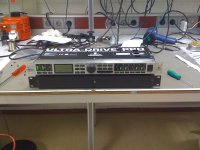
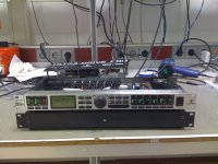
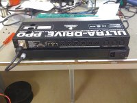
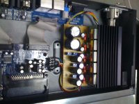
About going active, digital and the DCX2496 I could't agree more. First of all I highly believe in active loudspeakers, and filtering BEFORE the loudspeaker units. Second, I believe digital is the way to go, so you can not only do things easier and faster, but also safe yourself a lot of analogue noise contributing components in the signal flow. Second, I believe Behringer is a incredible value for money. Yes standard is doesn't sounds so good, but the software is good even as the DSP. The D/A converters aren't bad either, I like the AKM's. I prefer though to feed it digital. So being an DIY-er (else you would't end up on this forum after all) of course you should, must and want to modify the thing. There are topics enough about it, personally I would say change all the opamps and capacitors in in/outputs. Change the power-supply for a linear one. Change the clock for the up-sampler. I played around a little bit with a DCX2496 myself as well for fun. And modify it a bit as well like you can see in the attachments. Really way to go, and a lot of fun since you can easy tweak, and align your loudspeaker units with the DCX2496.
With kind regards,
Bas
About going active, digital and the DCX2496 I could't agree more. First of all I highly believe in active loudspeakers, and filtering BEFORE the loudspeaker units. Second, I believe digital is the way to go, so you can not only do things easier and faster, but also safe yourself a lot of analogue noise contributing components in the signal flow. Second, I believe Behringer is a incredible value for money. Yes standard is doesn't sounds so good, but the software is good even as the DSP. The D/A converters aren't bad either, I like the AKM's. I prefer though to feed it digital. So being an DIY-er (else you would't end up on this forum after all
) of course you should, must and want to modify the thing. There are topics enough about it, personally I would say change all the opamps and capacitors in in/outputs. Change the power-supply for a linear one. Change the clock for the up-sampler. I played around a little bit with a DCX2496 myself as well for fun. And modify it a bit as well like you can see in the attachments. Really way to go, and a lot of fun since you can easy tweak, and align your loudspeaker units with the DCX2496.With kind regards,
Bas
Attachments
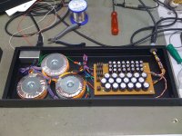
Oh I forgot, the gut's of the external power supply . Since it was only a one time for myself modification, I didn't bother to draw and make real PCB's but did all by hand on experimental boards The regulator stage is insidethe DCX2496, the transformer, rectification enz. outside.
. Since it was only a one time for myself modification, I didn't bother to draw and make real PCB's but did all by hand on experimental boards The regulator stage is insidethe DCX2496, the transformer, rectification enz. outside.Attachments
Hi,
Simple, restore the output impedance to the pre-change state. Add a series resistor between actual output (and NFB takeoff) but after the junction of the transistors emitter resistors.
Make sure the test is blind. I like to use two otherwise identical units.
If the two units still show the difference noted with different z-outs then Z-out was not the reason for the difference. One can then systematically eliminate the observable differences until the DUT's measure the same. Often (funnily enough) sonic differences still persist, showing that not all that can be measured matters and not all that matters is covered by common measurements.
I understand it is easy to draw such erroneous conclusions (like "I hear better/tighter/different bass and my change has increased DF, so this is the cause"). Yet this is mainly because years of advertising use of damping factor and the pick up on this by reviewers (who usually fail to understand the technology and just parrot manufacturers blurb) have in your mind created a link between "good bass" and "high DF".
For fun, I find extending the FR of a Speaker well into the ultrasonic brealm has a major impact on perceived bass response (lower and tighter), yet the frequencies concerned cannot even be heard as sinewaves. The effect persists with CD which has anything in that range chopped out too! Maybe your improvements in bass result from similar effects, rather then from DF?
Ciao T
Dear Thorsten,
Testing blind would be difficult since I don't have an ABX box. But I am open for it. Despite the marketing I do understand the meaning of dampingsfactor, how it is calculated, and how less there is left from it after all the added resistance from the amp till the voicecoil.
I remember I owned a Bryston 4B. And upgraded to the 7B monoblock. Which is in fact a bridged 4B but with a lower voltage rail. because of the bridging twice the slewrate, twice less dampingfactor. You could put this amplifier in parallel as well. My 7B's where less in bass then my 4B's. When I paralleled them instead of bridge my bass was awesome again. But yes I get your point. It isn't sure if this is because of the change in Z-out.
With kind regards,
Bas
It's ok Sebastiaan, I've now realised it's a very loosely moderated (un-moderated?) forum, so I don't mind anymore. When in Rome, do as Romans do
jcx - you have a point, I was perhaps too close-minded in my initial approach.
Thorsten, that crossover looks very, very promising indeed. It would allow tri-amping, it seems to be able to do everything that a crossover should do, and it's decently priced as well. But can it accept digital signal from a CD player? Or would I have to bypass its A/D circuitry somehow?
Coincidentally, the speakers I will be looking at tomorrow are three way, and tri-wireable. They are quite old (Mordaunt Short System 442), but in their time they were strictly hi-end - I'm hoping they can still beat most of today's mid-end speakers...
Edit:
I have come up with another idea: how about splitting the power amp into two 3-channel units, and and mounting them right on (or right next to) the speakers? I recall someone (maybe even Peter Daniel) said that Gainclones benefit greatly from short speaker cables. The trade-off here is of course a longer signal cable.
Why not built them on the back of your speakers and make a real active system? I am agree the shorter the speaker cables, the better. A longer signalcable is less worse then a longer speakercable. If you gonna use the DCX2496, give your gainclone a balanced input.
With kind regards,
Bas
Thanks Sebastiaan, I will definitely turn to you for help when I get to modifying my crossover
As for mounting amps on the back of the speakers though, I have mixed feelings. The reason for that is that I wouldn't want to expose the amp to vibration generated by speakers. I know it doesn't make much sense - it doesn't to me anyway... I mean I always thought that electrons will find their way across the cable no matter how hard you shake it...
But many respected audio designers (the guy who designed Gaincard among them) put great emphasis on controlling resonances. Peter Daniel got to the point where he claimed that using brass cone feet for the amplifier case improves sound; or that heatsink made of bronze "sounds" better than copper. These things may well be true, but I personally find them utterly perplexing. I mean I can see why would physical layout impact the sound, or the choice of wires, perhaps even case material - all these things could be causing some electric or electromagnetic phenomena (shielding or interfering in some way). But why would cone feet improve sound??
Thorsten - about this shielding sheet you linked - would it make sense to use it elsewhere around the amp? I know some people used thin copper sheets to shield the chip itself (ie. wrapped it around the chip and attached it to heatsink on both sides of the chip) - another idea I admit I like, even though many people claimed it did nothing to sonics. But I find it very appealing, if only because I would silver-plate the copper sheet first - so even if the sound remained unaffected, the looks would be far improved at a low cost. (remember that I love silver)
That brings me to the matter of silver wires again - can you describe their "sound" a bit further please? I would be really disappointed if I had to use copper instead of silver... so I hope you'll understand that I would like to know exactly why is silver not your suggested choice?
You expressed precisely what I was thinking.Second, I believe digital is the way to go, so you can not only do things easier and faster, but also safe yourself a lot of analogue noise contributing components in the signal flow.
As for mounting amps on the back of the speakers though, I have mixed feelings. The reason for that is that I wouldn't want to expose the amp to vibration generated by speakers. I know it doesn't make much sense - it doesn't to me anyway... I mean I always thought that electrons will find their way across the cable no matter how hard you shake it...
But many respected audio designers (the guy who designed Gaincard among them) put great emphasis on controlling resonances. Peter Daniel got to the point where he claimed that using brass cone feet for the amplifier case improves sound; or that heatsink made of bronze "sounds" better than copper. These things may well be true, but I personally find them utterly perplexing. I mean I can see why would physical layout impact the sound, or the choice of wires, perhaps even case material - all these things could be causing some electric or electromagnetic phenomena (shielding or interfering in some way). But why would cone feet improve sound??
Thorsten - about this shielding sheet you linked - would it make sense to use it elsewhere around the amp? I know some people used thin copper sheets to shield the chip itself (ie. wrapped it around the chip and attached it to heatsink on both sides of the chip) - another idea I admit I like, even though many people claimed it did nothing to sonics. But I find it very appealing, if only because I would silver-plate the copper sheet first - so even if the sound remained unaffected, the looks would be far improved at a low cost. (remember that I love silver
)That brings me to the matter of silver wires again - can you describe their "sound" a bit further please? I would be really disappointed if I had to use copper instead of silver... so I hope you'll understand that I would like to know exactly why is silver not your suggested choice?
Last edited:
- Status
- This old topic is closed. If you want to reopen this topic, contact a moderator using the "Report Post" button.
- Home
- Amplifiers
- Chip Amps
- A chip-amp to rival Hi-End - design advice