.....But does air blowing out of small ports orthogonally to radiation direction of trebles not cause modulation of trebles? You know the effect of wind blowing away sound.
You right but the data they have shown so far looks very good, and one thing that helps here is both bushmeister and xrk971 use probably less than 0,05 mili ohm output impedance power amps direct connected to tweeter and that will electrical stiff cone working as a brake against that wind blowing and the closer amp is to tweeter the shorter speaker cable will be and also helps in this regard. That is possible because they use DSP as XO and timing correction in front of power amp, but Tom Danley also explained somewhere here on diyA that on his passive XO'ed Synergy speakers he used a solution having a small value inductor directly across compression drivers terminals so as below XO point compression driver will be a electric short so as again to brake that wind blowing.
Last edited:
neglecting to remember that the "too small ports" as Grasso likes to call them behave like a low pass filters acoustically.
opening the woofer ports allows higher frequencies to escape and overlap the adjacent mid or high band.which could lead to problems
perhaps once more fully understood he may think differently.
opening the woofer ports allows higher frequencies to escape and overlap the adjacent mid or high band.which could lead to problems
perhaps once more fully understood he may think differently.
Ya, i get the thot: Horn must be big, but woofers must sit close to tweeter, so woofers inside horn.
But then, why small woofer ports? Why not let the diaphragms of the woofers form the outskirts of the horn, for instance ten small woofers circling around a circular horn? O.k., most woofer diaphragms are not straight or convex but concave, causing errors in the horn shape. But does air blowing out of small ports orthogonally to radiation direction of trebles not cause modulation of trebles? You know the effect of wind blowing away sound.
Why small woofer ports? Two reasons.
1. Efficiency! The MF and LF ports of Unity and Synergy horns are the exits of compression driver systems.
2. Acoustic low pass filtering.
I think "wind" is not really a factor because the air in the duct to exit port moves back and forth almost like solid unit - is bi-directional - whereas wind is a unidirectional flow. The ports don't really blow air like a fan.
So wesayso sent me a convolution file to try.
So I downloaded the trial version of Jriver. Downloaded the WAV file into the convolution box. And enabled the WDM driver. Then I selected Jriver as output in REW and ran some measurements.
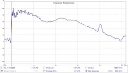
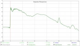
There is significant latency, so REW cuts off the top end - any ideas how I can get past that?
Anyway some initial results. I don't think the speaker and mic are in exactly the same spots, but some fairly impressive results nevertheless!
So I downloaded the trial version of Jriver. Downloaded the WAV file into the convolution box. And enabled the WDM driver. Then I selected Jriver as output in REW and ran some measurements.
There is significant latency, so REW cuts off the top end - any ideas how I can get past that?
Anyway some initial results. I don't think the speaker and mic are in exactly the same spots, but some fairly impressive results nevertheless!
Attachments
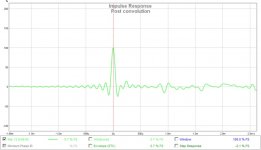
I've emailed you a couple of pointers on how to setup JRiver. We should be able to get this going, all the way up to ~18 KHz. There will be latency, as this is a phase correcting FIR filter with 65536 tabs.
Hope to see the full results soon. Take your time setting things right.
Hope to see the full results soon. Take your time setting things right.

Yep!!!
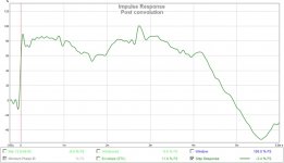
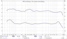
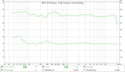
Amazing results - bearing in mind these measurements are taken 2.5m away from the speaker, in my study at the LP.
Amazing results - bearing in mind these measurements are taken 2.5m away from the speaker, in my study at the LP.
Attachments
You mentioned the speaker, nor the mic being in the exact same position. Now I'm not worried about the exact mic position, that's why we are testing a short filter(*) here. But technically the speaker should have been in the exact same spot. As well as anything in it's close environment.
But even with that disclaimer I think the power of FIR correction is already showing a little here. Did you listen to something? In mono? Something snappy... but with a good vocal?
(*) = Many tabs can't be a called a short filter, but what I meant by that statement is a relative short correction window.
The results here were with a target set to flat. For listening pleasure something else may be needed. The correction recipe used here is one optimized for my own speakers, and as such improvement may be possible by using slightly different settings.
Can't help but think these plots look kinda fake to me though...
Last edited:
Can't help but think these plots look kinda fake to me though...
To nice to be true from your point of view Ronald? Or is this some kind of irony?
Could you explain in plain word what your are trying to achieve and the method if it isn't too long to do?
Last edited:
To nice to be true from your point of view Ronald? Or is this some kind of ironie?
Could you explain in plain word what your are trying to achieve and the method if it isn't too long to do?
That was a bad joke, sorry. look for posts by a certain someone earlier in the thread.
What we did here was to use a short frequency dependent window to correct FR together with an even shorter window to correct the phase on the low end, extending just past the x-over. If the speaker is up to it (and in my view the Unity/Synergy is) this will actually work over a large listening area.
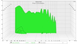
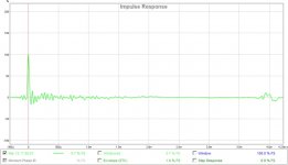
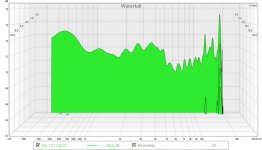
As is evident this correction clears up the early waterfall plot immensely. That is something you will notice in listening, no doubt. It's even beyond my expectation. Great to see that.
This is by no means a final result, as the setup is temporary. But it does show the things only FIR can do. This is speaker correction, more than room correction though you cannot avoid to have the room mixed in at the listening position. That's why you first need to make sure to solve things like early reflections, have a speaker that is consistent up/down and left/right. The Unity/Synergy can do that.
In a permanent setup you'd need to worry about toe in etc... to get the best of it, but due to the Harsh crossover and the low level of early reflections I figured this speaker was a prime candidate to show the potential.
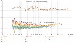
The early waterfall plot shows great potential. It is showing the diminished cone movement from the tweeter and the shared load of the woofers does work to get a really clean midrange and even a very clean top end. Would love to listen to a setup corrected like this.
Many more ideas to try and improve the listening experience though, but this should be a nice start.
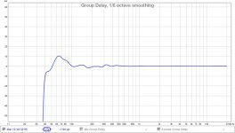
Ronald low limit of correction is set to approximately 100hz?
The FR correction is 20 hz to 20 KHz, the extra phase correction is using a shorter span, not correcting the top end. That part is more "in room" correction.
The waterfall only shows the first 3 ms.
If the speaker had been in the exact same position the FR would have been more flat in the ~500 Hz. Do not make to much out of this. It's nothing more than a quick demo. The STEP might have gone on for longer too. It would be wise to track down that early reflection and solve it in a more traditional/old fashioned way
.
Last edited:
The acoustic lowpass of second order is wrong, because its time error must be equalized by FIR filters. A good driver with shielded pole core does not distort much, hence no backend lowpass is needed. But if you think, that it is needed, then you should dig up up the old research done for bass-reflex ports, about how nonlinear air compression is, depending on SPL and frequency, and how turbulence at hard edges adds to that nonlinearity. No simulations please. It may be difficult computing turbulence in the brain, but if you cannot, then all you have is 131 pages of wank.
Yep!!!
Amazing results - bearing in mind these measurements are taken 2.5m away from the speaker, in my study at the LP.
.....Can't help but think these plots look kinda fake to me though...
Hardware and software cooperation looks great so far
Allow me believe i can see sample rate conversion (SRC) distortion in REW plot, if you can manage to get all hardware and software to be in exactly same sample rate setting under measurement then 250uS before and after IR will be even cleaner. In practice i mean because UMIK-1 is a locked device at 48kHz it will be steering setting for measurement so in windows sound settings set output device also to 48kHz plus set the two software pakages REW plus JRiver also at 48kHz. Feel free after that to use whatever settings but because of UMIK-1 48kHz locking then for measurement chain to be as clean as possible set rest of chain to same.
EDIT Forgot in above that also JRiver WDM virtual output device need tweaked to 48kHz.
Last edited:
That was a bad joke, sorry.
For me it's ok... make me grin.
What we did here was to use a short frequency dependent window to correct FR together with an even shorter window to correct the phase on the low end, extending just past the x-over. If the speaker is up to it (and in my view the Unity/Synergy is) this will actually work over a large listening area.
Ok i would have thought it could counteract the group delay of the acoustic lowpass the box represent for low end as it should be easily treated*, so my question about low fr of treatment.
* being closed box: close miked measurement of low end freq range could give final qts of box (because sealed one) then extrapolate the curve from sim for that. Don't know if my description is clear enough?
not correcting the top end
That make perfect sense: better to use some kind of absorber/redirecting panel for this part of specter.
It would be wise to track down that early reflection and solve it in a more traditional/old fashioned way
My bet this one is from the desk!
Last edited:
The acoustic lowpass of second order is wrong, because its time error must be equalized by FIR filters. A good driver with shielded pole core does not distort much, hence no backend lowpass is needed. But if you think, that it is needed, then you should dig up up the old research done for bass-reflex ports, about how nonlinear air compression is, depending on SPL and frequency, and how turbulence at hard edges adds to that nonlinearity. No simulations please. It may be difficult computing turbulence in the brain, but if you cannot, then all you have is 131 pages of wank.
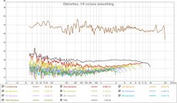
Please show a waterfall plot of the early signal of your speaker to compare.
Use settings like these:

These are measurements in room, try and top them... Can you? Regardless of what you think of the methods used, look at the results. That's the sound you're going to hear. Ah... why do I even bother to reply...
I finally know why this stuff you post gets under my skin, I have huge respect for the exiting things Tom Danley comes up with. Until you show you're worth it, I cant say I feel the same about your contributions.
The speaker moved, all bets are offOk i would have thought it could counteract the group delay of the acoustic lowpass the box represent for low end as it should be easily treated*, so my question about low fr of treatment.
. Phase correction is only valid at a single point. I'm not trying to correct all of it. Don't trust the REW group delay plot too much. Better to use APL_TDA for that i.m.h.o. In REW it's never going to be an exact representative.* being closed box: close miked measurement of freq r could give final qts of box because sealed one then extrapolate the curve from sim for that. Don't know if my description is clear enough?
Not sure what you're getting at here. This is a DRC-FIR correction with a home brew template from me based on a listening position measurement. Compare the results to the ones from this post: http://www.diyaudio.com/forums/multi-way/285030-bookshelf-multi-way-point-source-horn-127.html#post4644924
That's about as far as it goes. Testing conditions weren't ideal here
. That make perfect sense: better to use some kind of absorber/redirecting panel for this part of specter.
The FR was corrected up to 20 KHz, speaker correction with a very short frequency dependent window. Just not the phase part separately. But the phase still is more minimum phase than before this correction was applied.
That is evident in the STEP.
My bet this one is from the desk!
I wouldn't dare bet against you!
Hardware and software cooperation looks great so
Allow me believe i can see sample rate conversion (SRC) distortion in REW plot, if you can manage to get all hardware and software to be in exactly same sample rate setting under measurement then 250uS before and after IR will be even cleaner. In practice i mean because UMIK-1 is a locked device at 48kHz it will be steering setting for measurement so in windows sound settings set output device also to 48kHz plus set the two software pakages REW plus JRiver also at 48kHz. Feel free after that to use whatever settings but because of UMIK-1 48kHz locking then for measurement chain to be as clean as possible set rest of chain to same.
EDIT Forgot in above that also JRiver WDM virtual output device need tweaked to 48kHz.
My correction was a quick job, which had is own conversion from 48000 to 44100, so that would be me.
Bushmeister knows it's sub-optimal (I think).Don't blame him, that's my doing, I didn't have the files ready for 48000 as I run all my corrections at 44100. Only my DAC up-samples but I never could live with up-sampling everything in JRiver, for whatever reason. It just sounds a bit off to me for whatever reason. Never bothered to look into it.
I did try a long time ago, even though the plots seemed cleaner, my ears said something else. These plots are average representatives and need to be picked apart to tell the complete story. Especially the IR. That's why we need so many different ways to look at it.
Last edited:
Not sure what you're getting at here.
Wasn't sure to be clear enough too!
But you partially answered my question: DRC. I've seen FIR used to 'correct' phase behavior of closed box acoustic lowpass behavior. what i was trying to explain was related to this: as net volume of XBush box is approximated, in order to determine qtc (then the groupdelay intended of couple box/speaker) and verify it correlate to FIR correction done. But it's different that what you are doing: DRC.
That is the reason i asked about a description of your 'routine'/ method.
I wouldn't dare bet against you!
This time you could as this is pure assumption and shot in the dark! All that can be said is that this is a reflection which traveled approximately 1.3/1.4 meter more distance than initial signal.
Could be some side wall or ceiling ER too.
- Home
- Loudspeakers
- Multi-Way
- A Bookshelf Multi-Way Point-Source Horn