Okay. I should have rephrased that question of mine, making it clear that I don't want to use plate amps and active crossovers. I want to just build a simple 2-way passive crossover with the baffle step in mind and the notch filter that I already built for the FE103E's.
Ok you should reread the entire thread
")
But I can summarize :
It is hard to make a passive crossover with a frequency of 100Hz as explained. An active solution is easy.
I don't recommend to use a 4" at 100Hz because of power handling. The P21 can support 80W and the 103E 5W ! You will burn your fostex, or it will not be very at ease ! Usually we use a 8" or 2x7" as midrange if we go down 100Hz ... I recommend a crossover frequency 400-800Hz. My simulations work well with a second order crossover as I wrote (with the values). You don't need the notch filter. The result will be better than the fostex cut at 100Hz, if it was easily feasible.
I think you should test our proposals, we have some experiences with multiway systems
.Have fun !
I'd have to agree.
Low frequencies don't lend themselves to passive crossovers. A series capacitor has next to no effect at resonance, where there's a large impedance peak.
The values of components will be large, so extra series resistance (particularly from an inductor) won't help things, but is likely to screw up the bass response - under the "signal" tab on winISD, add 2ohm of series resistance, see where that takes you.
A first order crossover won't be steep enough to protect the little Fostex from over-excursion (and power) anyway, so going active seems to be the way to do it: you can use much steeper slopes easily, and tweak them at little cost.
Chris
Still no chance to make & post a series vrs parallel circuit and do't see freeing up time any time soon. Google is your friend.
1st pass on an XO (based on nominal 8 ohms) with your 51 uF caps is series with 5 to 13 mH. 51 + 5 gives you ~300 Hz XO with zeta 1.2, moving to larger inductor moves the XO down and zeta up (51 + 12, 200 Hz, Zeta 1.9). If you have any more caps you can move the XO down and the zeta closer to 1 (butterworth).
dave
But I can summarize :
It is hard to make a passive crossover with a frequency of 100Hz as explained. An active solution is easy.
I don't recommend to use a 4" at 100Hz because of power handling. The P21 can support 80W and the 103E 5W ! You will burn your fostex, or it will not be very at ease ! Usually we use a 8" or 2x7" as midrange if we go down 100Hz ... I recommend a crossover frequency 400-800Hz. My simulations work well with a second order crossover as I wrote (with the values). You don't need the notch filter. The result will be better than the fostex cut at 100Hz, if it was easily feasible.
I think you should test our proposals, we have some experiences with multiway systems
Have fun !
When I was running both of these Fostex drivers before (103 & 126), I was using an active x-over at 36dB per, so running them at 80Hz wasn't that much of a problem.
Now that I'm going passive ONLY, I have no issues going to 400-800Hz x-over points. So I can totally bypass the notch filter I have now and just use a cap in series with the Fostex driver like you say, correct?
What about the Vifa driver and the baffle step? What would need to be done there?
I'd have to agree.
Low frequencies don't lend themselves to passive crossovers. A series capacitor has next to no effect at resonance, where there's a large impedance peak.
The values of components will be large, so extra series resistance (particularly from an inductor) won't help things, but is likely to screw up the bass response - under the "signal" tab on winISD, add 2ohm of series resistance, see where that takes you.
A first order crossover won't be steep enough to protect the little Fostex from over-excursion (and power) anyway, so going active seems to be the way to do it: you can use much steeper slopes easily, and tweak them at little cost.
Chris
When I get home tonight I'll play around in WinISD some to see what I come up with along with the crossover calculators.
Still no chance to make & post a series vrs parallel circuit and do't see freeing up time any time soon. Google is your friend.
1st pass on an XO (based on nominal 8 ohms) with your 51 uF caps is series with 5 to 13 mH. 51 + 5 gives you ~300 Hz XO with zeta 1.2, moving to larger inductor moves the XO down and zeta up (51 + 12, 200 Hz, Zeta 1.9). If you have any more caps you can move the XO down and the zeta closer to 1 (butterworth).
dave
Thanks Dave, I just haven't had time either to do any "Googling", but I will this weekend. And from what you guys are telling me (which makes perfect sense BTW), I will be going with a higher x-over point.
Now that I'm going passive ONLY, I have no issues going to 400-800Hz x-over points. So I can totally bypass the notch filter I have now and just use a cap in series with the Fostex driver like you say, correct?
What about the Vifa driver and the baffle step? What would need to be done there?
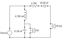
This is a schema as simple as possible. The crossover point is near 500Hz.
The baffle step is corrected with a big coil 4.7mH. You must adjust the level of the Fostex, it is the job of the 4.7 ohms resistor. This value of this resistance can vary for fine tuning. The capacitor 22uF cut near 500Hz, it push the 100Hz resonance effect only 15dB down. Note the fostex is in opposite polarity.
The capacitor 51uF is by default because you have it, you can remove it, to test but not recommend. This capacitor can be replace by an impedance compensation R=6.8 C=15uF, but I think a simple capacitor is more efficient. A value near 27uF gives a better phase response, eventually to test ?
You will be very busy this week-end
Attachments
Great info and schematic Jerome. Thanks!
I have a quick question for you guys as I'm getting ready to start some cutting in a few minutes. Hopefully someone will answer between now and when I get done doing the measuring and cutting.
The Dayton crossover that's in these towers right now have x-over points of 375Hz/3kHz @ 12dB per. I was thinking of using the woofer output on the crossover for the Vifa (just for now until I get the actual parts to build my own) and using the Solen 51uF caps on the Fostex drivers just to get me by for a while even though it obviously won't be optimal. I just want to get these drivers up and running again.
So I have at my disposal (2) Solen 51uF caps, (2) 1mH inductors and (2) 3 ohm resistors, the last two of which were from the notch filter used on the Fostex drivers before.
What would the effective crossover frequency be of the FE103E drivers with the 51uF caps and possibly the 1mH inductors be? This would essentially get me a 12dB per octave slope, but I would like to know if it gets me close enough to that 375Hz woofer x-over point. According to the x-over calculator, a 51uF cap in series would get me around 390Hz, but that's only 6dB per.
Last edited:
What are the values of the dayton crossover for the woofer ? I want to calculate the real crossover point. These crossovers are generic ! We could use your existing components.
You should only use in series the resistor and the capacitor. The inductor is useless.
Be aware if the electrical filter is 6dB, the acoustic slope could not be 6dB but 12dB. We work with acoustic slope.
You should only use in series the resistor and the capacitor. The inductor is useless.
Be aware if the electrical filter is 6dB, the acoustic slope could not be 6dB but 12dB. We work with acoustic slope.
What are the values of the dayton crossover for the woofer ? I want to calculate the real crossover point. These crossovers are generic ! We could use your existing components.
You should only use in series the resistor and the capacitor. The inductor is useless.
Be aware if the electrical filter is 6dB, the acoustic slope could not be 6dB but 12dB. We work with acoustic slope.
All I can see are two 26mF caps and one 40mF cap that looks to be in the woofer end of things. In the mid and treble section they use decent Dayton film caps. I don't know the value of the iron-core inductor.
You should only use in series the resistor and the capacitor. The inductor is useless.
Also, why is the inductor useless?
Sorry Dave, but I'm totally lost.
I want to keep this as simple as possible just for now until I get the parts to build my own crossovers.
Right now, the Vifa is still connected to the low-pass output of the Dayton crossover (roughly 375Hz).
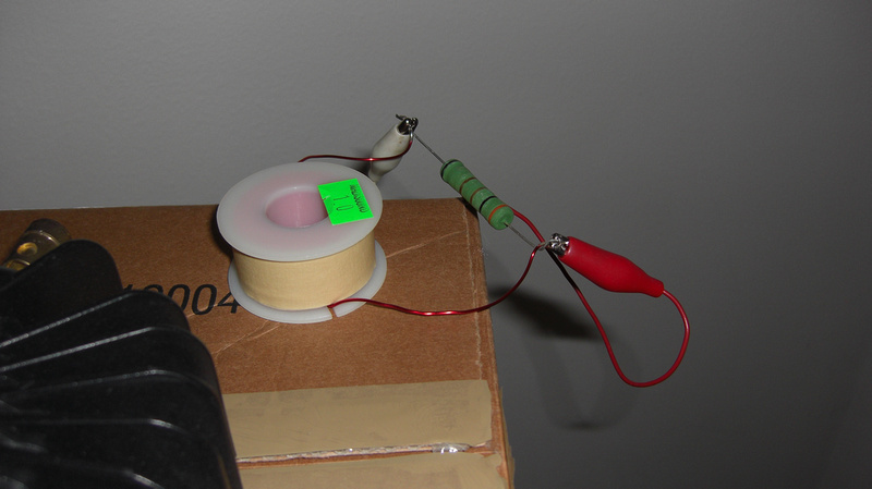
Can't I just run another wire straight to the Fostex from the input with the 51uF cap on the (+) leg for the desired 390-ish Hz point? And if I use the 3 ohm resistor, would I run that between both terminals of the Fostex, or in series with the cap, and before or after the cap?
The resistor is the same exact one in the picture a couple posts above.
I'm at a stand-still at the moment because I don't know how to wire the Fostex up... Other than that, the speakers are pretty much done and ready to go.
I want to keep this as simple as possible just for now until I get the parts to build my own crossovers.
Right now, the Vifa is still connected to the low-pass output of the Dayton crossover (roughly 375Hz).
Can't I just run another wire straight to the Fostex from the input with the 51uF cap on the (+) leg for the desired 390-ish Hz point? And if I use the 3 ohm resistor, would I run that between both terminals of the Fostex, or in series with the cap, and before or after the cap?
The resistor is the same exact one in the picture a couple posts above.
I'm at a stand-still at the moment because I don't know how to wire the Fostex up... Other than that, the speakers are pretty much done and ready to go.
Nothing simplier than i suggested that gives you a hope of something coherent.
0/ Take the iron core inductor out of the XO. Set aside the XO.
You will need 5 alligator clips (or 5 pieces of wire).
1/ Using 2 of the clips, connect the inductor across the FE103.
2/ Using 2 of the clips, connect the capacitor across the woofer
3/ Using the 5th one, connect the minus of the FE103 to the plus of the woofer.
4/ Hook the amp up to the plus of the FE103 & the negative of the woofer.
Crossover should be fairly co-herent, FE103 likely a bit louder than the woofer. At this point you can insert a resistor between the amplifier + inductor connection (lift them of the plus on the FE103) and the + on the FE103e. If you get larger than 4 ohms you will likely need an L-Pad instead of a resistor (an L-Pad for playing is likely not a bad idea)
dave
Use it doesn't give a good phase response although the resonance of he fostex is better controlled. Don't forget to connect the fostex in opposite polarity.Also, why is the inductor useless?
Follow Dave instructions or my schematic.I'm at a stand-still at the moment because I don't know how to wire the Fostex up... Other than that, the speakers are pretty much done and ready to go.
Have fun.
Here's the crossover in question. I don't know how to go about getting these inductors off, or which ones to use as the crossover is set up to use either 4 ohm or 8 ohm drivers with a blade fuse as the jumper.
The top left iron-core inductor has four taps coming off of it, which I'm assuming is for the 4/8 ohm operation. Below it are two 26mF/100V caps. Next over is the 40uF/100V cap. Next is an air-core inductor with a 3uF/250V film cap below it. Another large iron-core inductor but with only two taps, another 3uF/250V film cap, then another air-core inductor.
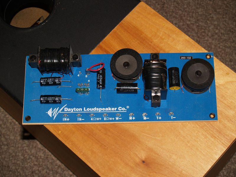
The top left iron-core inductor has four taps coming off of it, which I'm assuming is for the 4/8 ohm operation. Below it are two 26mF/100V caps. Next over is the 40uF/100V cap. Next is an air-core inductor with a 3uF/250V film cap below it. Another large iron-core inductor but with only two taps, another 3uF/250V film cap, then another air-core inductor.
Last edited:
You use a solding iron to remove the inductors. Sounds like you have 3 differnt inductors that you can try.
They can also be seriesed & paralleled for different values. A multimeter with an inductance bridge would help with a little light, but just measuring the impedance would sort them into small, medium & large Iif the wire is all the same size)
dave
They can also be seriesed & paralleled for different values. A multimeter with an inductance bridge would help with a little light, but just measuring the impedance would sort them into small, medium & large Iif the wire is all the same size)
dave
Hi Dave,
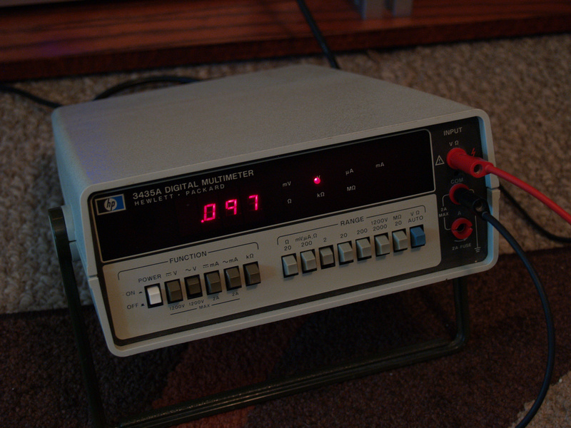
This is the DMM I have to work with. Will it do?
Also, it looks like I'll have to drill out those rivets to get that backing off of the XO board in order to desolder the components.
Just took the backing off, clipped all the leads as there's huge clumps of super hard glue all over the back of this thing, and all the inductors are riveted on. A major PITA. Gonna try drilling through the rivets now...
Last edited:
- Status
- This old topic is closed. If you want to reopen this topic, contact a moderator using the "Report Post" button.
- Home
- Loudspeakers
- Multi-Way
- A 2-way tower with Vifa woofer and Fostex FE103E...