Hello sneha,
Dont go with any pcb design.
So much people are uploading bad design.
So much errors and all,
Just sir mile( apex audio) designs are tested himself...so you can use it with trust......🥃🥃🥃🥃
I suggest you to make your own pcb design...
Btw, come soon back,
I agree 100 %
thats why I have design myself Class D UcD PCB from schematic Mr. Kartino
Dont think its easy like class AB/H,
also you need PCB design software to proof PCB routing mistakes V/S schematic otherwise sure you will get first time smoke
Be aware to buy amplifier PCB from 3th party, make it self
I losing time and money, and be aware to buy IR Mosfet driver, Power Transistor in epay if you design amplifier
buy from mouser, digikey, farnell, tme, lcsc and you will have working amplifier
Thank you so much sandeep sir and NMOS,
You guys are right....i found some mistakes on pcb design
And yes sandeep sir i am coming soon.
Thank you ones again,,
Btw sandeep sir your amp,,, i like it.even i'll also do same thing..
Hello sir mile,
I just wanted ask if use 0-55-110vdc bridge mode, how much AC V comes out....at normal clip...
Does anyone know who design this pcb ???
how about sound sir??
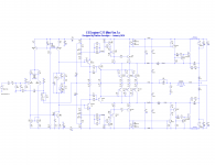
hi all the new td version by kartino .
have fun all
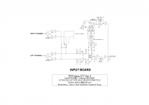
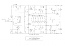
TD (TRACKING DIGITAL) & E-ENGINE AMPLIFIER
TD (TRACKING DIGITAL) & E-ENGINE AMPLIFIER
have fun all
TD (TRACKING DIGITAL) & E-ENGINE AMPLIFIER
TD (TRACKING DIGITAL) & E-ENGINE AMPLIFIER
Attachments
@stewin,
you asked Yamaha for permission to use their design ?
for learning purposes
hi all the new td version by kartino .
have fun all
TD (TRACKING DIGITAL) & E-ENGINE AMPLIFIER
TD (TRACKING DIGITAL) & E-ENGINE AMPLIFIER
updated version by kartino
EEEngine
Attachments
Last edited:
hi all the new td version by kartino .
have fun all
TD (TRACKING DIGITAL) & E-ENGINE AMPLIFIER
TD (TRACKING DIGITAL) & E-ENGINE AMPLIFIER
Stewin,
please upload the lt-spice file if possible.
Thank you!
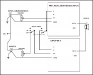
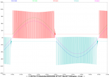
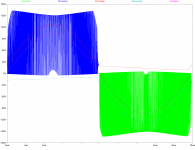
Sir Mile, what is going on? H900 bridge mode, just 20 Vac but spkr pump good but.....
Your step driver not work, there must be 40vac on output.
Mistake Pa protection
Hello,
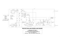
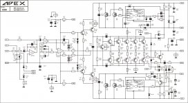
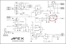
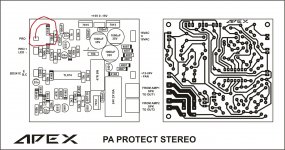
Sir Mile, i found a difference between the circuit and the PCB of Pa protection.
Diode 4148 surrounded in red is connected in the circuit with the anode to the "pro" output of the amplifier. On the PCB, this diode has a cathode to the "pro" output.
Which option is correct or do both options work?
Hello,
Sir Mile, i found a difference between the circuit and the PCB of Pa protection.
Diode 4148 surrounded in red is connected in the circuit with the anode to the "pro" output of the amplifier. On the PCB, this diode has a cathode to the "pro" output.
Which option is correct or do both options work?
Attachments
Hello,
Sir Mile, i found a difference between the circuit and the PCB of Pa protection.
Diode 4148 surrounded in red is connected in the circuit with the anode to the "pro" output of the amplifier. On the PCB, this diode has a cathode to the "pro" output.
Which option is correct or do both options work?
Anode to the 'pro' is correct.
Please sir, pm me password and details.password and detail please inbox , thanks

- Home
- Amplifiers
- Solid State
- 900W H-class PA Amp with Limiter