Tested at 15Hz and trigger at 25vrms.Now try 18Hz, and/or 16Hz, and/or 14Hz.
Does it trigger?
Does it trigger at a lower output voltage?
Are these lower frequency triggers acceptable to you?
BTW, you don't need the 7r0 dummy load. The detector is only detecting DC and very long duration
portions of the output voltage. It is not detecting current. That is done in a different part of the protection system.
Tested at 10Hz and trigger at 17vrms.
At these frequencies the protection led flashes slowly.
I see that thermal protection and d.c protection wasn't independent each other ,i will prefer a separate stage for d.c protection.
I see that thermal protection and d.c protection wasn't independent each other ,i will prefer a separate stage for d.c protection.
May be an other op amplifier or a transistor circuit .
Last edited:
That fits with my experiments.
As a result I moved my full power trigger frequency down to 15Hz.
I then checked the time to trigger for a DC level from 0Vdc to 10Vdc.
The filter slows down the detect and trigger as the DC signal goes lower.
But I got around 3seconds for a 1.5Vdc +ve offset, slightly higher for a -ve offset.
Virtually instantaneous for 10Vdc + or -.
Did you resolve WHY the 22uF did not trigger. Was it down to excess leakage?
I see that when the thermal detector transistor is not connected at all then circuit was trigger event with 22uf.That fits with my experiments.
As a result I moved my full power trigger frequency down to 15Hz.
I then checked the time to trigger for a DC level from 0Vdc to 10Vdc.
The filter slows down the detect and trigger as the DC signal goes lower.
But I got around 3seconds for a 1.5Vdc +ve offset, slightly higher for a -ve offset.
Virtually instantaneous for 10Vdc + or -.
Did you resolve WHY the 22uF did not trigger. Was it down to excess leakage?
That is the reason gives me the opinion for a separate stage.
Hi,
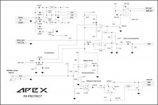
I would change the 150k and the 220k resistors at the DC detection. The detecting transistors shoul conduct 5mA for the triggering, which means some base current, which makes large DC drop on the mentioned resistors.
I would use 22-33k instead of the 150k, and same instead of the 220k.
Sajti
I would change the 150k and the 220k resistors at the DC detection. The detecting transistors shoul conduct 5mA for the triggering, which means some base current, which makes large DC drop on the mentioned resistors.
I would use 22-33k instead of the 150k, and same instead of the 220k.
Sajti
If you are right then the circuit is crap. It should not be designed such that the hFE of the chosen transistor stops, or allows, the circuit to work.Hi,
I would change the 150k and the 220k resistors at the DC detection. The detecting transistors shoul conduct 5mA for the triggering, which means some base current, which makes large DC drop on the mentioned resistors.................
I see that when the thermal detector transistor is not connected at all then circuit was trigger event with 22uf.
That is the reason gives me the opinion for a separate stage.
Go to post #3271
If you are right then the circuit is crap. It should not be designed such that the hFE of the chosen transistor stops, or allows, the circuit to work.
Agree. I use BC546B/556B with 47k, and much Power current for triggering.
Sajti
I made a mistake in post 3291.
I said without a switching transistor.
I should have noticed that it's the first driver transistor that is omitted and replaced with a comparator.
That comparator does NOT need 5mA at either of it's inputs to turn on the 2n5401.
I said without a switching transistor.
I should have noticed that it's the first driver transistor that is omitted and replaced with a comparator.
That comparator does NOT need 5mA at either of it's inputs to turn on the 2n5401.
Last edited:
Agree. I use BC546B/556B with 47k, and much Power current for triggering.
Sajti
Sorry:Much less current for triggering (500uA).
Sajti
Even 500uA (0.5mA) seems wrong, for the trigger current into the comparator.
Is it worth checking again?
When I use a 2transistor switch I arrange for the switching transistor to run saturated, i.e. Ie:Ib ~= 10:1
For a 40mA relay that would require a 4mA Ib.
The driver transistor then runs with a typical hFE of 100 to 300. The worst case driver Ib would be ~4mA/100 ~40uA
If I use bc550b for both, I expect driver Ib ~10 to 20uA, no where near your estimate of 500uA.
Last edited:
Even 500uA (0.5mA) seems wrong, for the trigger current into the comparator.
Is it worth checking again?
When I use a 2transistor switch I arrange for the switching transistor to run saturated, i.e. Ie:Ib ~= 10:1
For a 40mA relay that would require a 4mA Ib.
The driver transistor then runs with a typical hFE of 100 to 300. The worst case driver Ib would be ~4mA/100 ~40uA
If I use bc550b for both, I expect driver Ib ~10 to 20uA, no where near your estimate of 500uA.
I use comparator, which is acting as a Schmitt trigger, with 4V hysteresis. This do the start up delay too. I use 10kohm series resistor at the input of the comparator, which means 400uA trigger current to reset the relay. (Not 500uA, sorry I was remember wrong).
400uA collector current for the sensing transistors means approx. 4uA base current, as the transistors can work in the 4-8V range, so saturation is not necessary.
4uA will drop 0.132V on the filter resistor (33kohm).
Sajti
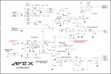
I have modify circuit according to this schematic.No it isn't functional.DC protect circuit without transistors.
Now it is trigger at +9v d.c and it wasn't trigger at any negative voltage.
I have modify circuit according to this schematic.No it isn't functional.
Now it is trigger at +9v d.c and it wasn't trigger at any negative voltage.
Replace 470k with 47k...
YesHave you built it according to Apex sch?
- Home
- Amplifiers
- Solid State
- 900W H-class PA Amp with Limiter