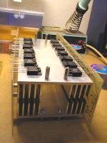
This is good size for 2U case.230 / 75 mm
I designed the PCB to be used in active subwoofers with built-in amplifier
Feedback trace missing...I removed all limitations on the input side, you mean PCB design mistakes or mistakes in the electrical diagram?
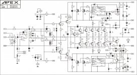
Doing that is all about limiting the gain the the output stage. You just can't run outputs open loop, switch them, and expect stability. The in Original QSC circuit, the output CFP's are configured as FOLLOWERS, and there are only two stages of current gain. (Do this with three, and you must go to triple EF. Don't just take my word for it - try it, build an oscillator/bomb, and then post the results.)The output section appears to have "gain", but only by virtue of the op amp, which is itself unity gain stable. The newer PLX circuit's output section has local feedback, with a gain of less than 20 with the rest provided by an op-amp. The PLX circuit actually sounds better than the original in practice - but I wouldn't expect the first PCB layout you try to work. And it requires very careful adjustment of the bias for thermal stability. These circuits have been simulated to death and have been refined over 20+ years. The powerlights don't all use the same approach - the new ones are class D.
If you switch EF output stage in open loop it will remain stable, same is the case with unity gain CFP, i have tried both approaches, but the moment you put some GAIN in output as in CFP the stability is compromised. Like in QSC PLX series they are limiting the slew of step switch to preserve stability because the output is having gain. In old QSC such as MX and RMX series the output stage is grounded collector type and is having unity gain, so there is again no problem in stability.
If you compare old MXa series with newer PLX series the old ones are more reliable, i have seen amplifiers working from past 15 year without a single fault but same is not case with newer generation amps of QSC. MXa series is that amplifier who has made qsc's reputation in reliability.

Switching losses are resonable with TL072, but mosfet need cooling by heatsink. With IR2117 mosfet can work without heatsink, but no need to risk. I suggest circuit with TL072 just in case IR2117 is not available.
IR2117 circuit is more reliable as it operates the mosfets with minimum losses due to faster speed. It has been used in many amplifiers which are even 3 to 4 steps class-H.
There are many alternative gate driver chips on market if IR2117 is not available. One can try these:-
FAN7361
&
FAN7371 for high current bigger mosfets.
wg_ski----If you use the IR2117, you can get that down to 50ns. But I wouldn't.
A RC snubber across Drain to Source terminal of FET helps in achieving controlled slew slope when IR2117 or FAN7371 is used.
mur120, byd73d, byv26c...bav21 fast switching diode do-35 , 250v
any other info of these diode
are there any family of this one like the in_ _ _ _
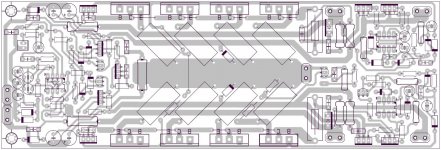
Can U marked values? Fets on positive side wrong direction.checked and fixed ,other mistakes ?
Last edited:
hi engel, i get fast recovery rectifiers from discarded pc monitors, you will be surprised how many parts you can take out from those....http://www.datasheetcatalog.com/datasheets_pdf/B/A/V/2/BAV21.shtml
Last edited:
hi engel, i get fast recovery rectifiers from discarded pc monitors, you will be surprised how many parts you can take out from those....BAV21 Datasheet pdf - Small Signal Diodes - General Semiconductor
sir tony,
i manage to get back to back diode instead of sfa1603
also from pc psu
this bf 421 or mpsa92
nsl32 or any opto
and this bav21
this is my head ache
sir can i use two 1w 15v zener if i did'nt manage to get 2w?
sir tony,
i manage to get back to back diode instead of sfa1603
also from pc psu
this bf 421 or mpsa92
nsl32 or any opto
and this bav21
this is my head ache
sir can i use two 1w 15v zener if i did'nt manage to get 2w?
engel, to be able to come up with substitutes, you must understand how a particular component functions in a given circuit....what current and voltage will it see? how fast is the signal going to be? analysis of the circuit allows you to see this.....
afaik, zeners are 1/2w, 1, and 5watts, if you know how much power a zener will dissipate in a circuit, then you can decide for your self.....
See post #230hi apexaudio
greetings posted pictures of solder side any mistakes let me know
and how to power up amplifier
thanking you
andrew lebon
Attachments
- Home
- Amplifiers
- Solid State
- 900W H-class PA Amp with Limiter