I can see the kink where the straight section mis-aligns with the curved section. But look at this Mazda datasheet from Frank's, the kink is quite obvious on it. Your copy has had the kink smoothed over.
http://frank.pocnet.net/sheets/020/e/EC86.pdf
"gm" is the derivitive or slope of the Vg1 versus Ip curve, it would have to be constant in the region where the line is straight. But isn't.
But comparing the variation in the gm curve thru that region with say the EC88 or 6BQ7.... would give a good comparison for relative linearity between the tubes. As you say, the PC86 may well be better. But it is not perfect as the phony straight curve would indicate.
Last edited:
No matter where I locate that "curve" on the monitor, I see an obvious kink. You have to look down it at a grazing angle to the screen surface and along the line to see the discontinuity.
http://frank.pocnet.net/sheets/020/e/EC86.pdf
OK, it does look better on the laser printer, but I still see a kink when looked at along the line at surface grazing angle.
http://frank.pocnet.net/sheets/020/e/EC86.pdf
OK, it does look better on the laser printer, but I still see a kink when looked at along the line at surface grazing angle.
Last edited:
OK Don, you see a kink, I see a straight line. Others here can check, and see for themselves, if it's of any value.
But the overall excellent performance from this driver design remains. And alternative means of achieving the same end usually suffer from much worse drawbacks.
The biggest drawback with shunt cascode is that it is difficult or impossible to build point-to-point, sadly. The huge gain means you have to make it very small, and use ferrite chip-beads to keep it stable.
But the rewards are obvious, when the needle hits the groove.
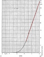
Lets look at the actual data it shows. I took these data points at the ends of the straight section:
34.6 mA at 0 Vg1
12.5 mA at -1.475 Vg1
computing the slope: (34.6 - 12.5) / (0 - 1.475) => - 14.983 mS
while the gm curve (Philips PC86 datasheet) shows 15 mS at 15 mA where the curve ends unfortunately. But for the Ip versus Vg1 line to be straight on up to 34.6 mA, the gm curve would have to flat top at 15 mS, from 15mA on up.
http://frank.pocnet.net/sheets/030/p/PC86.pdf
The coincidence that the gm, Rp, and u data end at 15 mA, where the "ruler straight" curve section begins, tells me they faked the rest of the "curve".
Last edited:
And I see a kink in both of them at 13 mA.
No point in arguing really. I would not trust any datasheet for accuracy good enough for accurate distortion analysis anyway. An FFT on the soundcard is the only way to tell accurately. I just see so many tube datasheets with sloppy data curves, more like French curves. But straight line extrapolated curves with no support data are just too much. Probably half of the TV sweep tube datasheets have the kinks near the plate curve knees (just above them) edited out.
No point in arguing really. I would not trust any datasheet for accuracy good enough for accurate distortion analysis anyway. An FFT on the soundcard is the only way to tell accurately. I just see so many tube datasheets with sloppy data curves, more like French curves. But straight line extrapolated curves with no support data are just too much. Probably half of the TV sweep tube datasheets have the kinks near the plate curve knees (just above them) edited out.
Last edited:

")
Now we can see clearly, that over the operating swing of the PC86 Shunt Cascode driver (11 - 17mA) the transfer characteristic is as linear as we could wish for.
And, given the huge gain, I have omitted any cathode bypass capacitor - meaning it will be linearised further, if it were needed.
And, given the huge gain, I have omitted any cathode bypass capacitor - meaning it will be linearised further, if it were needed.

ECC88 looks like it has more curvature than the PC86. Rod has clearly chosen the best tube.
I hate to ask for more tests (thank you so much for these already!), but in case its a slow day there, some other tubes that might be interesting to compare for cascode use (maybe Rod has some too):
6E5P (this one was in the Bartola writeup on Rod's circuit)
12HL7 (edit: never mind on this one, I see the GE datasheet has this curve)
6BQ7 (edit: never mind on this one, I see the GE datasheet has this curve)
I should get my Tek tracer fired up here. I only have the 12HL7 and 6BQ7 available here though.
http://frank.pocnet.net/sheets/093/6/6BQ7A.pdf
http://frank.pocnet.net/sheets/135/1/12HL7.pdf
Last edited:
@Rod Coleman,
why do you use a CCS ? The triode anode is on a constant voltage from the P-MOS so the difference Va and Vpower is fixed.A resistor will pass a constant current there.
Or from an other point of view,the anode is charged with almost zero ohm and the extra load from a resistor (not that small) makes no difference as long as the needed current is suplied.
Mona
- Status
- This old topic is closed. If you want to reopen this topic, contact a moderator using the "Report Post" button.
- Home
- Amplifiers
- Tubes / Valves
- 813 and gm70