Hi Ian,
It was somewhat arbitrary, but probably comes down to the consideration that 8mA/V gives a gain of 100, even with only 12K or so of output resistor. If high gain is not needed, Shunt Cascode starts to look complex, if an ordinary triode with CSS load stage will suffice.
It was somewhat arbitrary, but probably comes down to the consideration that 8mA/V gives a gain of 100, even with only 12K or so of output resistor. If high gain is not needed, Shunt Cascode starts to look complex, if an ordinary triode with CSS load stage will suffice.
Yeah, I thought it might have been a rule of thumb sort of thing but just wanted to make sure it wasn't a trail sign that some of your higher wisdom was lurking in the shadows, unseen.
Not long ago I built a little differential 6336 amp using the 6BX7 as input/driver mostly because I'd done one years before and liked the sound of the combination. But the 'bx' doesn't have the gain I want and have been thinking it might be neat to try a version of your circuit to kick it up a bit.
The amp circuit as is is IT coupled and that's what I've been wondering about.
When I first read your descriiption of the circuit I had the thought that it might drive it well provided the IT is good enough and the circuit designed well (or luckily, in my case!). But now I wonder. If the shunt cascode's output gain is gm*Rl then where XL is frequency dependent, gain would vary too, no?
"If the shunt cascode's output gain is gm*Rl then where XL is frequency dependent, gain would vary too, no? "
Normally there would be some grid bias resistor to set a load impedance (with XL well above that hopefully, maybe). Or a load resistor intentionally put across the secondary to control resonances.
------------------------
Since recently noticing that the (upper) curvature of gm versus Vg1 is dependant on the filament voltage for some valves, it occured to me that this may be what people are hearing when they "burn in" new tubes. The new cathode is probably overly emissive, and some burn in time likely lets it settle down some, with the result that the gm curve straightens out some (giving less distortion).
I was able to straighten out the curve of a new 6JT8 pentode (triode configured), and even bend it backwards with reduced filament voltages (28% and 40% reduction of filament V).
It might be interesting to re-visit the curve tracer plots for the PC86 and 6E5P valves with say 25%, 40% reduced filament voltage. Since these were close to flat curves to begin with, they may even curve in the opposite sense at lowered filament voltages. (Adalin still tuned in?) If one had a brand new tube versus a used tube (so somewhat reduced emission maybe) to compare, and saw the same effect, this would be quite convincing evidence for a real "burn-in" effect. (or curve measure a new tube, then burn it in for some decent time, then re-measure the curve.)
If so, then one might be able to instantly "burn in" a tube by just reducing its filament voltage some. This would make the tubes last a bit longer too. Although one would likely want to restore the full filament voltage after the usual burn time had passed. One might even want to "tune up" an amplifier with a variable filament voltage knob(s) and a sound card FFT. (Might be just a switch to put some SS diode pairs in series.) Line voltage variation could also explain some effects on amplifier sound, although not just filament V would be involved then.
Last edited:
Yeah, I thought it might have been a rule of thumb sort of thing but just wanted to make sure it wasn't a trail sign that some of your higher wisdom was lurking in the shadows, unseen.
Not long ago I built a little differential 6336 amp using the 6BX7 as input/driver mostly because I'd done one years before and liked the sound of the combination. But the 'bx' doesn't have the gain I want and have been thinking it might be neat to try a version of your circuit to kick it up a bit.
The amp circuit as is is IT coupled and that's what I've been wondering about.
When I first read your descriiption of the circuit I had the thought that it might drive it well provided the IT is good enough and the circuit designed well (or luckily, in my case!). But now I wonder. If the shunt cascode's output gain is gm*Rl then where XL is frequency dependent, gain would vary too, no?
Hi Ian,
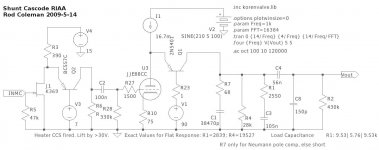
Yes, the output of the shunt cascode (before the load resistor is connected) is a pure current. So a reactive load would certainly produce frequency variation: eg a capacitor produces low-pass filtering.
This effect is exploited nicely in the RIAA shunt cascode stage.
R1 R4 C1 C3 set the RIAA curves, and because they are driven by a current, there's no need for any series-resistor. Also, there is no worry over the anode-slope resistance corrupting the eq, as there is in normal stages.
Attachments
Don, some useful observations.
Another possible inquiry: maybe starving the filament of a nice power valve, (eg triode connected PL84 - 15CW5 with its 10mA/V) would also give us a linearised high current region.
Other power valves allow high voltage operation, which extends the range of Shunt Cascode applications.
Another possible inquiry: maybe starving the filament of a nice power valve, (eg triode connected PL84 - 15CW5 with its 10mA/V) would also give us a linearised high current region.
Other power valves allow high voltage operation, which extends the range of Shunt Cascode applications.
Very nice indeedHi Ian,
Yes, the output of the shunt cascode (before the load resistor is connected) is a pure current. So a reactive load would certainly produce frequency variation: eg a capacitor produces low-pass filtering.
This effect is exploited nicely in the RIAA shunt cascode stage.
R1 R4 C1 C3 set the RIAA curves, and because they are driven by a current, there's no need for any series-resistor. Also, there is no worry over the anode-slope resistance corrupting the eq, as there is in normal stages.

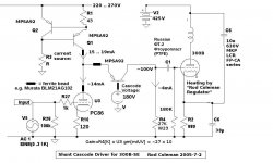
I see you have the two solutions in one circuit,a resistor and stable voltage for the current in the first stage and a CCS in the second.
It looks like Tube on the beach, a lot of sand and little bit of tube
Mona
As far as burning in valves is concerned, my usual experience is that I have to keep turning down the volume, sometimes quite dramatically and often over an extended period before it settles. Surely this means that the cathode emission is low to start with? This is particularly marked with high gm valves.
Is this for NEW valves, or NOS valves? I would certainly expect NOS valves to have reduced emission from gas absorption on the cathode. Will take a while for the getter to clean the vacuum and surfaces up. Possibly new valves would show the same phenomena if the vacuum as manufactured was not that good (gettering time needed).
I did try a NOS 21LG6 TV horizontal tube with reduced filament voltage, and this just reduces the current I can get out of it. It does show some improvement in the gm/Vg1 linearity above +Vg1, but with a worse curvature at lower currents. I think the power tubes may be too optimised for high gm, so have too much curvature (grid wire proximity effect) to fix readily. Some frame grid signal tubes may work though.
Probably not a technique that will work for most power tubes.
Last edited:
Hi Ian,
Yes, the output of the shunt cascode (before the load resistor is connected) is a pure current. So a reactive load would certainly produce frequency variation: eg a capacitor produces low-pass filtering.
This effect is exploited nicely in the RIAA shunt cascode stage.
R1 R4 C1 C3 set the RIAA curves, and because they are driven by a current, there's no need for any series-resistor. Also, there is no worry over the anode-slope resistance corrupting the eq, as there is in normal stages.
Alright, that's enough! You keep throwing that schematic out there/here, I'll do it. I'm not sure how much it will have to change for the 7963 but let's see. I have weekends free for a few weeks so I'll make up a board and try it out. I saw that you are big on ferrites though not sure where. On plate and grid I'd guess, yes? Gate and base stops . What else would you add here?
Weren't you going to do some boards ? `,;^)
He He! you know you want to! This drawing shows the important positions for ferrite chip-beads, and the type I used then. The Murata -AG grade should do it, for today's procurement.
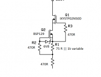
A depletion FET CCS is probably easier and better, too. May be easier with 470R of resistance in the CCS ouput too.
Yes, I've done a PCB, but every time I sit down to finish the characterisation, it gets pushed aside by some industrial work!
A depletion FET CCS is probably easier and better, too. May be easier with 470R of resistance in the CCS ouput too.
Yes, I've done a PCB, but every time I sit down to finish the characterisation, it gets pushed aside by some industrial work!
Attachments
Yeah, yeah, you're right. Don't gloat!
Those Murata filters are pretty tiny, no fun for anybody with nothing but a 300 watt soldering gun. (You know, the ones with a headlight that turns on when you pull the trigger. . . . . ) Will this or this be an appropriate sub?
I understand the easier, but why better? I thought you were a fan of bipolar junction transistors.
BTW, I took note of your comment on the NXPs and I thought I'd use one for the cascode position. The Z package is still small for hand soldering but easy compared to that Murata bead . . . . . . and if it does go tink! when I turn it on, I won't say you made me do it!
Those Murata filters are pretty tiny, no fun for anybody with nothing but a 300 watt soldering gun. (You know, the ones with a headlight that turns on when you pull the trigger. . . . . ) Will this or this be an appropriate sub?
,A depletion FET CCS is probably easier and better, too. May be easier with 470R of resistance in the CCS ouput too.
I understand the easier, but why better? I thought you were a fan of bipolar junction transistors.
BTW, I took note of your comment on the NXPs and I thought I'd use one for the cascode position. The Z package is still small for hand soldering but easy compared to that Murata bead . . . . . . and if it does go tink! when I turn it on, I won't say you made me do it!
The Bourns beads may be OK, if they are wired with very short connexions. Worth a try, if you are willing! Try to set the arc-welder on level-1.
Depletion FET current sources are impeccable - (a) for this current level, and (b) when having 20-50V headroom is easily achieved.
Depletion FET current sources are impeccable - (a) for this current level, and (b) when having 20-50V headroom is easily achieved.
Hi
I incorporated Rod’s driver, using a EF184, into a friend’s amps, with amazing results! I had learnt a lot on the way though- i.e. I had a few issues, which Rod helped me with! In particular-
Increase the grid stopper to 33k or 47k to further stifle possible oscillation. Because of the way the circuit works, Miller capacitance isn’t an issue. I also fitted ferrites and 1k CC resistors both on the CCS’s output and as an anode stopper.
Put a reverse biased 1N4148 diode across the shunt transistor’s be junction, to protect from reverse overvoltage during power on. If you don’t do this, its performance deteriorates with time
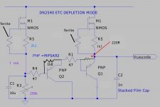
I used the depletion FET CCS circuit attached (thanks to Paul Hynes for this). I ended up feeding this from a voltage regulator, and had to put something like a 1k/47u RC filter before it to stop oscillation- though this might not have been necessary in the final version. Whichever CCS you use, it takes 20 -30 min for the current to stabilise and for the output voltage swing to be finally optimised. It seemed pretty stable after that. With the FET design, from memory, when set up the voltage on the 27k resistor starts about 30 V low and slowly increases to the required ½ anode voltage. The BJT design, it starts close to the anode voltage and the drops. If you want to listen immediately, the FET circuit thus offers an advantage
Unless you bypass the driver’s cathode resistor with a suitable capacitor- which Rod describes as “sonically ruinous” (!) the gain of the driver stage will be a lot lower than R4 x gm. Rod can supply a spread sheet to calculate how much lower. With an EF184 and a 130R cathode resistor, the gained dropped by about 1/3, I think. Thus input sensitivity may be a little lower than ideal. Dropping the value of the cathode resistor increases it, but hen anode current can rise unacceptably. With the EF184/130R, plate and g2 dissipation were about 75% of max. Some EF184’s are fine long term with this, but some fail rather quicker than I’d like. I’ve found them to very variable out of the box, even after burn in and the elimination of grid current issues. If I still had the amps to hand I might try replacing the cathode resistor with a MPSA92 with a red LED as the voltage reference on the base; the LED could be fed ~ 10 mA from a suitable RC supply derived from the stage supply, to give a 2.3- 2.4V cathode voltage, and a very low cathode impedance- i.e. full gain restored
Hope this helps. As I said the circuit works excellently in practice, but just requires a little effort to make it stable. BTW I won’t see an email after tomorrow for two weeks, if you have any questions. I’ve also attached the circuit of the cascode supply I used- I sure better is possible
Best wishes
Paul N
I incorporated Rod’s driver, using a EF184, into a friend’s amps, with amazing results! I had learnt a lot on the way though- i.e. I had a few issues, which Rod helped me with! In particular-
Increase the grid stopper to 33k or 47k to further stifle possible oscillation. Because of the way the circuit works, Miller capacitance isn’t an issue. I also fitted ferrites and 1k CC resistors both on the CCS’s output and as an anode stopper.
Put a reverse biased 1N4148 diode across the shunt transistor’s be junction, to protect from reverse overvoltage during power on. If you don’t do this, its performance deteriorates with time
I used the depletion FET CCS circuit attached (thanks to Paul Hynes for this). I ended up feeding this from a voltage regulator, and had to put something like a 1k/47u RC filter before it to stop oscillation- though this might not have been necessary in the final version. Whichever CCS you use, it takes 20 -30 min for the current to stabilise and for the output voltage swing to be finally optimised. It seemed pretty stable after that. With the FET design, from memory, when set up the voltage on the 27k resistor starts about 30 V low and slowly increases to the required ½ anode voltage. The BJT design, it starts close to the anode voltage and the drops. If you want to listen immediately, the FET circuit thus offers an advantage
Unless you bypass the driver’s cathode resistor with a suitable capacitor- which Rod describes as “sonically ruinous” (!) the gain of the driver stage will be a lot lower than R4 x gm. Rod can supply a spread sheet to calculate how much lower. With an EF184 and a 130R cathode resistor, the gained dropped by about 1/3, I think. Thus input sensitivity may be a little lower than ideal. Dropping the value of the cathode resistor increases it, but hen anode current can rise unacceptably. With the EF184/130R, plate and g2 dissipation were about 75% of max. Some EF184’s are fine long term with this, but some fail rather quicker than I’d like. I’ve found them to very variable out of the box, even after burn in and the elimination of grid current issues. If I still had the amps to hand I might try replacing the cathode resistor with a MPSA92 with a red LED as the voltage reference on the base; the LED could be fed ~ 10 mA from a suitable RC supply derived from the stage supply, to give a 2.3- 2.4V cathode voltage, and a very low cathode impedance- i.e. full gain restored
Hope this helps. As I said the circuit works excellently in practice, but just requires a little effort to make it stable. BTW I won’t see an email after tomorrow for two weeks, if you have any questions. I’ve also attached the circuit of the cascode supply I used- I sure better is possible
Best wishes
Paul N
Attachments
Hi
Sorry- I posted the wrong CCS circuit! I use IXTP02N50D on top, BSP129 below (Paul Hynes' design). Don't have the exact circuit to hand- will post if I get a chance. I use versions of this in both stages of my phono amp, and in my line stage, at currents from 5 mA to ~ 20mA. superb performance and sound
Paul N
- Status
- This old topic is closed. If you want to reopen this topic, contact a moderator using the "Report Post" button.
- Home
- Amplifiers
- Tubes / Valves
- 813 and gm70