We already see portion of audio band at -92dbV DUT/instrument combined noise floor (0dbV=1VRMS), -72dBV hum at 50Hz. You only got a 100Hz portion though. There is a menu that selects bandwidth, and there is a generator menu that selects test frequency.
That 50 Hz hum is actually audible with the ear in the cone. It was my meaning to work that away but I got hooked on measuring gear for some reason instead
")
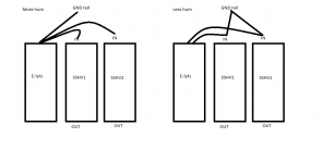
I was a bit puzzled on how to work the groundrail best with the SSHVs a bit remote from the app. I first had filter ground rail to last lytic pack and then to SSHVs with thin copper. When I changed to thicker copper and wired filter-SSHV-last filterpack the groundhum more then halfed.
Attachments
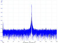
Seems its too low a frequency range for its sampling rate and deep memory to resolve well in high bin count. The noise floor looks like its Pico's own because the THD is buried in there. Only the hum is visible. Until learning ARTA and the like programs on a 24bit good audio card to exactly see, for now your build does not look high THD. Maybe if you push the input level but I doubt the Pico gen having any big output. If you will employ the Wavetek for that you will end up seeing its own sinewave THD mainly which is usually at 0.5% to 1% from lower to higher range for general use wide band function generators.
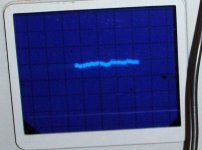
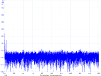
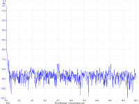
That looks bad! If it works well and your measurement method is good, it should look like a flat line. The attached image, an hv shunt reg of my own, at 500uV/div.
Yes Im sailing again. I thougt Ive solved that but apperently it came back. Its ground relatez since its the same b4 and after SSHV. Now get kiddo
That looks bad! If it works well and your measurement method is good, it should look like a flat line. The attached image, an hv shunt reg of my own, at 500uV/div.
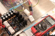
Well, I did a new PSU today.
I started to misstrust the other trafo and the AZ1 that closes up to its limits. Its a C-L-C followed by double R-C to each SSHV. They get 330 V in with about 85 mV ripple in, measured with both DMM and scope. SSHV out is 270 VDC and 76 VRMS. I have set current testpoints at 0,400 V for 40 mA.
Dummyload is 13k5 on each SSHV for 20 mA.
Are the SSHVs malfunctioning? Where shall I search?
@ Stajo
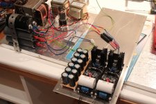
Your #1746 post shows some undulation at about 0.32mS period. That is 3100HZ. Too high for being hum too low for being oscillation. In your #1752 picture I see long input cabling and some central GND node to it. Decouple the regs inputs right across their +IN/0V connector with small film caps and see if there is a problem with the raw DC part grounding scheme by trying alternatives.
Your #1746 post shows some undulation at about 0.32mS period. That is 3100HZ. Too high for being hum too low for being oscillation. In your #1752 picture I see long input cabling and some central GND node to it. Decouple the regs inputs right across their +IN/0V connector with small film caps and see if there is a problem with the raw DC part grounding scheme by trying alternatives.
As I say above: "They get 330 V in with about 85 mV ripple in, measured with both DMM and scope. SSHV out is 270 VDC and 76 VRMS."
But I ment ofc 76 mVRMS ripple out
When driving one MegOhm input (or ten MegOhm for probe X10) from milliOhm source impedance you have a very receptive measurement loop to any kind of interference also. Use the short point ground coil instead of your GND crock. Remeasure. See if you get the same waves. See with and without remote sense. Although you use self made SSHV1 also that does not usually employ sense wires. Give us a clear account of the above so we can know the problems.
Attachments
Use the short point ground coil instead of your GND crock. Remeasure.
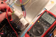
I've got this crap to measure HV
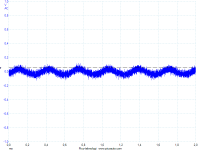
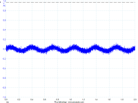
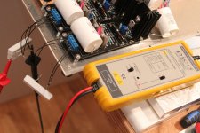
And some pix on ripple out. First with noice unfiltered, second with a 10 kHz lowpass filtering
Attachments
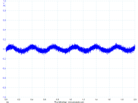
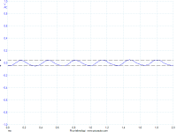
Can it read HZ at mV level? Press the frequency button for input and output probing. Its suspiciously same level for in and out now, it could all be riding on the ground loop. Dress the long output cables in twisted pairs. Force pair, sense pair. Remeasure. Null the sense pair by jumpers at F0,S0 F+,S+. Remeasure.A 10 uF over each. Ripple in and out
- Home
- Amplifiers
- Tubes / Valves
- 6V6 line preamp