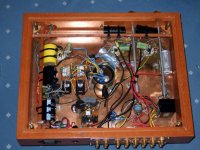
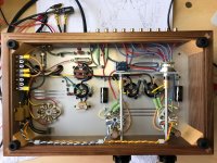
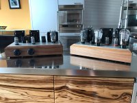
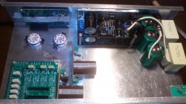
Just finish the Salas Preamp, I did the power supply different, I treated it like a power amp sense it's using a power amp tube. The heaters are AC and elevated to 60v. The tube sockets are decoupled from from top plate with rubber grommets. I spent many weeks on parts placement and wire routing.


Just finish the Salas Preamp, I did the power supply different, I treated it like a power amp sense it's using a power amp tube. The heaters are AC and elevated to 60v. The tube sockets are decoupled from from top plate with rubber grommets. I spent many weeks on parts placement and wire routing.
Beautiful build. Looks like its the gain version. Is it alright with ripple noise, hum etc given the AC heaters and passive rail filter without any active regulator following?
Beautiful build. Looks like its the gain version. Is it alright with ripple noise, hum etc given the AC heaters and passive rail filter without any active regulator following?
Thanks Salas, That means a lot to me!!!
Yes its the gain version. I needed gain to drive a 2A3/45 amplifier I built.
It is completely quiet no hum what so ever. Believe me I was a little worried but after reading that people successfully did elevated AC heaters I decided to give it a try. The rails are pretty clean with a 10H choke and 100uF caps right at the load resisters of each channel its definitely not starved and is very stable. I'm sure your active regulated power supply has a lot of benefits over the passive supply I built but I wanted to keep it as simple as possible and with as few parts as possable.
When a particular build gives no trouble in a particular system (power amp voltage gain + speakers sensitivity) its alright. Did you have chance to listen enough by now?
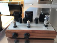
I finished it yesterday morning, It played all day yesterday and has been on all day today. It sounds better and better each hour but the tubes and everything is brand new. The sound continues to surprise me, I keep hearing things I didn't hear before. It's driving a 45 amplifier 1.5 watts into Marten Logan Montis at 93db Efficient. It will be going to my vacation home where I have a pair of Klipsch Heresy at 99db effecent. so i should see more gain. I can turn it up all the way without distortion. The impedance of the amp is 390k so I used a .22 uf cap instead of the .68 so I could make sure I can get to 20Hz.
Its a compatible system for it as I can tonally picture it. Should play nice Jazz especially. Also beautiful to behold as separates and as total. BTW try 200mS (5HZ) coupling sometime too if you would think deeper tone than now could be a plus. Not because of practical extension but due to measurably less phase turn at the audible bottom region.
Congratulations and keep us posted.
Congratulations and keep us posted.
I'm trying to find good oriedation....
That is a really hard question to answer. Design is always a mix of art and science. I have a few strict rules that I never break and others that can get a little gray.
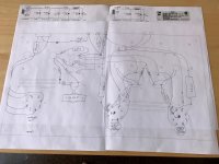
I would get out some paper and keep re arranging until you find the best posable location for each component and don't stop at 20 or 30 tries, do it until you know it's the best that can be achieved, then you will have it as good as you can get. It could take a few weeks or more but that is how a well though out plan is created.
Think of it like plumbing and what each wire/component is doing and carrying and take that into account through out the design.
Good luck! It looks like its going to turn out really nice
A small question the choke are total in H 10H or 5H each of them?
Thanks for the complement!
Each channel has a 10H choke with a 100x100uF cap between it tied directly to the load resister of each channel. The preceding part of the supply is shared. CRC
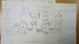
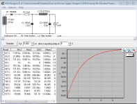
Finnaly I chose make this power supply.. sec 2X300ACV(230ma) and 2X10ACV(1A)
with two choke 10H (102Ω)
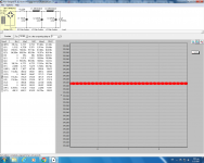
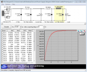
in PSU designer you should set your "after a reporting delay of" to 5 or something more than 0, so you can see where things will be once it's had a chance to power up.
This is what I did, I split the rails after the second 16uF cap, This is only showing one side (l1 would also have R2,C3, L1 and C4).
Salas says 20H for the chokes before the regulator and the regulator is to be shared with both channels so you should be fine with what you have.
Attachments
Μark you follow this topology for rectifier tube and 50 VAC..?
Yes, basically it is the same concept. you can see the HT schematic in my last post, you will need to adjust R1 until you get 340v, I had to adjust it to 2k2 but all that will depend on your transformer and rectifier.
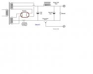
Here is the schematic for the 50v DC elevation. The transformer I used (Hammond 376X) has a 50v tap. Again you can adjust R1 until you get the desired DC to float your AC on. the center tap of the 6.3 winding connects to C2. I also put a .500ohm resister on each leg of the 6 volt tap to give me 6v AC (It was 6.9, to high for me)
Attachments
Mark you think that by using tube rectifier instead diode 1N or UF , SS diode, HV regs and AC for filaments the preamp sounds better?
I don't really know. I think the way Salas did it with the tube rectifier and HV regs is probably the way to go. I only did it different because I wanted to keep it as simple as possible.
- Home
- Amplifiers
- Tubes / Valves
- 6V6 line preamp