Decrease R4. but why would you want it without the global loop?
I was just trying to make it as low-distortion as possible before applying global NFB. Also, stability concerns. I'd rather not go crazy with little compensation caps, ferrite beads, etc.
As an option, 6AU6 for the first stage, 6AH6 for driver tubes. Nice cheap sleepers. Cheap 7-pin sockets. Also, 6AU6 triode strapped for Concertina.
All good ideas, of course.
Is 6AC7 basically identical in specs to 6AH6? If so, is there a problem using those? I have a bunch of them.
I have plenty of 6AU6, but no 6AH6 in my collection.
Or Soviet 6J4P for the first stage, 6J5P for the rest. Even cheaper, but still nice.
I'd use those if I had them. I do have some 6J51P (similar to EF184). Would those be useful as the LTP driver?
______________________________
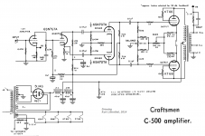
PS - I should really build a pair of these RCA 50 watt amps. It seems all the real engineer types love this design.
Last edited:
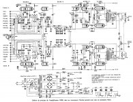
and anybody have a advice for my schema precedently posted ?
Modern Chinese fashion.
good advice,bad advice,no advice ?
We don't know your criteria. Without criteria there is no optimization. Such schematics are usually starting points for DIY based on bought in China cheap tube amps, cheaper than parts bought separately, including good looking chassis. How does it sound? What do you want to improve?
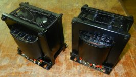
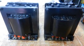
I've picked a Rowe-Ami recently and I modified it for use in hifi with a couple of 7591 and I enjoyed working on this device.
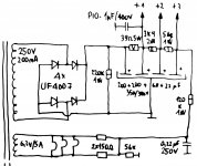
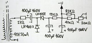
I bought a second that I want to mount in 6l6 or 6p3S-e and i'm looking for a simple schema, clean and stable for this new amp, but I seek above all to learn and understand.
I bought a second that I want to mount in 6l6 or 6p3S-e and i'm looking for a simple schema, clean and stable for this new amp, but I seek above all to learn and understand.
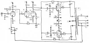
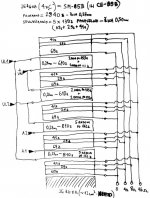
I see, since the tube characteristics are different, you may need to change the drive circuit and/or the feedback network, but it should be pretty straight forward. The last schematic that you posted requires another tube to be added, which is probably too much work, so you might as well start with the original Rowe-Ami design and make some changes.
Basically, you need to change the bias for the 6L6's (from -18.5V to say -26V), which you can do easily by changing the 10k to a pot, so the bias voltage can be adjusted. Depending on the input sensitivity, you need to change the feedback resistor (1.5k) to suit.
In addition, to optimize the load line for the 6L6's, you may want to lower the screen voltage a bit, by disconnecting the screen grids from the B+, and changing the first 1k-1W resistor to say 3.9k-2W coming off the rectifier, and re-connecting the screen grids to the second filter capacitor.
In addition, to optimize the load line for the 6L6's, you may want to lower the screen voltage a bit, by disconnecting the screen grids from the B+, and changing the first 1k-1W resistor to say 3.9k-2W coming off the rectifier, and re-connecting the screen grids to the second filter capacitor.
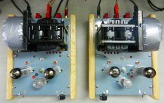
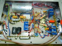
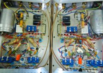
Monoblocks based on 2x6P41S and 6U10 in UL push-pull output amplifier with Pout more than 15W (~22W at start of clipping!).
Attachments
The Craftmen is indeed a good design, but it would require adding two more tubes and lots of re-wiring.I think I found the winner")
- Status
- This old topic is closed. If you want to reopen this topic, contact a moderator using the "Report Post" button.
- Home
- Amplifiers
- Tubes / Valves
- 6P41s vs 7868