Certainly, but with differences.Hello,
did someone tried the 6n6p ltp ,please ?
(b+=250v RT=RA=10k Rk=430r)
regards
Same B+, plate load 22k, CCS in tail.
Excellent driver for the EL34 output stage.
Hello,thanks for reply.Certainly, but with differences.
Same B+, plate load 22k, CCS in tail.
Excellent driver for the EL34 output stage.
would you help me please :
did you measure thd and gain ?
I need a 40v voltage swing to drive a g807 PP
Gain of a LTP is same as the gain of a common cathode stage, when input is between grids and output is between plates.
Gain of common cathode is u*RL/(RL+ra) where RL is the connected load and ra is the plate resistance.
If you look at output of one plate only, gain appears to be half.
Gain of common cathode is u*RL/(RL+ra) where RL is the connected load and ra is the plate resistance.
If you look at output of one plate only, gain appears to be half.
hello ,Certainly, but with differences.
Same B+, plate load 22k, CCS in tail.
Excellent driver for the EL34 output stage.
It seems that your phase splitter with 22k ra gives less h3 than my one with 10k.
Is it the same value of Ra for both triodes ?
have you a pot in front of them ?
Please.
Regards
Bonjour Artosalo,
J'aurais aimé en savoir plus.
Mais je ne suis pas assez équipé.
J'ai besoin d'un compteur de distorsion.
Je me suis appuyé sur Vtadiy pour trouver les valeurs.
Après, si vous le souhaitez, je peux effectuer quelques manipulations sur le montage. Demande moi.
Regards
J'aurais aimé en savoir plus.
Mais je ne suis pas assez équipé.
J'ai besoin d'un compteur de distorsion.
Je me suis appuyé sur Vtadiy pour trouver les valeurs.
Après, si vous le souhaitez, je peux effectuer quelques manipulations sur le montage. Demande moi.
Regards
"J'ai besoin d'un compteur de distorsion."Bonjour Artosalo,
J'aurais aimé en savoir plus.
Mais je ne suis pas assez équipé.
J'ai besoin d'un compteur de distorsion.
Je me suis appuyé sur Vtadiy pour trouver les valeurs.
Après, si vous le souhaitez, je peux effectuer quelques manipulations sur le montage. Demande moi.
Regards
Logiciel REV + carte son pas chère
(google translated, hope it makes sense
")
Thanks"J'ai besoin d'un compteur de distorsion."
Logiciel REV + carte son pas chère
(google translated, hope it makes sense
The Vdc is low. The bias current is too low.
Please don't use the trimmer to balance the ac signal, it is a critical stuff in that position.
With a proper test set: audio card + Arta or Rew and an attenuator you can check exactly the swing and Thd of both waves so you can trim the Voltage just to put a resistor in parallel on one anode.
With a proper bias point the value of Vac remain costant for many time.
Of course a proper selection of tubes is needed.
I have done a strong Ltp with 6H30 with 400 Vdc and around 10 mA each section.
Walter
Attachments
There are many free "Audio analyzer" software to download to your PC. Then you can measure THD and much more.Bonjour Artosalo,
J'aurais aimé en savoir plus.
Mais je ne suis pas assez équipé.
J'ai besoin d'un compteur de distorsion.
Je me suis appuyé sur Vtadiy pour trouver les valeurs.
Après, si vous le souhaitez, je peux effectuer quelques manipulations sur le montage. Demande moi.
Regards
Hello,The Vdc is low. The bias current is too low.
Please don't use the trimmer to balance the ac signal, it is a critical stuff in that position.
With a proper test set: audio card + Arta or Rew and an attenuator you can check exactly the swing and Thd of both waves so you can trim the Voltage just to put a resistor in parallel on one anode.
With a proper bias point the value of Vac remain costant for many time.
Of course a proper selection of tubes is needed.
I have done a strong Ltp with 6H30 with 400 Vdc and around 10 mA each section.
Walter
I'm now waiting for a soundcard.
I need a 50v output signal .
I changed the Anode loads and the grid resistor:
18K and 22k (21.5k).The 2.2k pot is usefull to adjust the output signals.
Rk=430 ohms, RT stays at 10k
Gain is 6.4 , vg= -4.14 v (mesured).
i can't increase so far the B+ but 290v is possible.
It seems difficult to do better...
regards
![IMG_20221211_211925_2[1].jpg](https://www.diyaudio.com/community/data/attachments/1026/1026866-a1f00efcc7e978cb89a757aaf35ac9fb.jpg "IMG_20221211_211925_2[1].jpg")
Hi
Walter
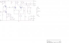
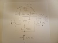
can you write down the last circuit with voltages on main points?Hello,
I'm now waiting for a soundcard.
I need a 50v output signal .
I changed the Anode loads and the grid resistor:
18K and 22k (21.5k).The 2.2k pot is usefull to adjust the output signals.
Rk=430 ohms, RT stays at 10k
Gain is 6.4 , vg= -4.14 v (mesured).
i can't increase so far the B+ but 290v is possible.
It seems difficult to do better...
regards
View attachment 1118957
Walter
As soon as possibleHi
can you write down the last circuit with voltages on main points?
Walter
HelloSalut
pouvez-vous écrire le dernier circuit avec des tensions sur les points principaux ?
Walter
Attachments
Hi
I use a higher Vdc
You go at 320-360 Vdc
And the use of the trimmer in that position for me is not fine. The contact with current will degrade
For me a good current for each section will be 7/8 mA
With 6H30 with similar circuit I run with 400vdc and the swing is perfect. Of course the resistor are to be well defined
For this I use to put in parallel a high value to fix the equal voltage on both section
- Home
- Amplifiers
- Tubes / Valves
- 6N6P tube - focus on