O have a project in the works that will use them. That does use a power triode. So far, one design used 807s as pentodes, the other 6BQ6s (TV HD power finals). Pents aren't hard loads, and even modest cathode followers are up to the task of driving the grids.
my observation too...maybe this year i will do the mosfet follower...
The OPT for the 200 watt test was 3300 ohms. A 2500 ohm OPT brought somewhere around 250 watts but the efficiency dropped indicating that the tubes were not happy.
thanks tubelab, i have a 3.5k OPT made for those tubes, i will be content to run them over the 100 watt range secured in the knowledge that they can deliver more if called upon...
I've been messing around with my 1625's two different ways. The biggest reveal is that my FLUKE power supply won't deliver anything over 400VDC with over 100ma. I have plenty of other ways for making HV. In any case, I've tried the 1625's using a Talema 12V/115/115V toroid wired in reverse as a grid driving element. I use a small parasound amp to drive the 12V winding with a lot of step-up to the grids. The center of the 115/115V windings is tied to a bench supply for Bias which happens to top out at -32VDC. The Toroid has a surprisingly high bandwidth driven this way. I've been able to get 57Watts at less than 2% THD (I'm lucky enough to have an Audio Precision system one) with 500V on the plates, 300 On G2, 4.3k load. Connected as triodes with 400V on the plates, same load I get about 35W at 2%, with nice overload to over 50watts.
Watching grid drive, The grids start going positive around 12-15watts which is the same neighborhood as a classic 807 williamson. My Speakers are UREI 811's with sensitivity to spare. I may go the lower powered Triode connection. Do these power levels sound about right for an 807/1625? Should I worry about 400 V on G2 in triode mode?
Watching grid drive, The grids start going positive around 12-15watts which is the same neighborhood as a classic 807 williamson. My Speakers are UREI 811's with sensitivity to spare. I may go the lower powered Triode connection. Do these power levels sound about right for an 807/1625? Should I worry about 400 V on G2 in triode mode?
IIn any case, I've tried the 1625's using a Talema 12V/115/115V toroid wired in reverse as a grid driving element. I use a small parasound amp to drive the 12V winding with a lot of step-up to the grids. The center of the 115/115V windings is tied to a bench supply for Bias which happens to top out at -32VDC. The Toroid has a surprisingly high bandwidth driven this way. I've been able to get 57Watts at less than 2% THD
What does that THD look like? When developing the design for an 807 amp, I found that running open loop, the THD spec of 1.8% was spot on. However, the Twin-T test showed a residual signal at 3X the fundamental that looked like an almost perfect sawtooth. Lots of high order harmonics there. Listening while open loop was excruciating. Lots of "fingernail on a blackboard" dissonance that quickly wore you out. These 6L6-oids definitely require the assistance of NFB if they are to sound good. For my design, I split that NFB between local parallel feedback, as recommended by the designer of the type himself: O. Schade, and gNFB. It would be very difficult to include an IST inside a gNFB loop, and you will be needing one.
If you insist on going that route, you might be better off going with 6BQ6s. The designer of this plate modulator went with this type where you'd expect to see 6L6s because 6BQ6s sound better without NFB. That's why I chose the 6BQ6 for another "junk box" project. While doing an open loop Twin-T test, the residual came in at 2.9% and looked like a slightly distorted sine wave: mostly h3 with a trace of h5. 6BQ6s sound overly "edgy" or "aggressive" open loop, but with none of that pentode nastiness until you're nearly at clipping. All these need is some gNFB to take the "edge" off.
Connected as triodes with 400V on the plates, same load I get about 35W at 2%, with nice overload to over 50watts. Watching grid drive, The grids start going positive around 12-15watts which is the same neighborhood as a classic 807 williamson. My Speakers are UREI 811's with sensitivity to spare. I may go the lower powered Triode connection. Do these power levels sound about right for an 807/1625? Should I worry about 400 V on G2 in triode mode?
Yes, the power levels seem normal. 400V on the screens is 133% over spec. At least as pseudotrides, the screens will be moving with the plate, and so won't see the very low plate voltages when the plates are pulling max current. As for whether or not this will work, no way to tell. YMMV. You might find that some 6L6-oids are OK with the spec bust, and some others might melt down on you.. If you try it, keep an eye on the screen grids. What you don't want to see are these glowing red hot. Major warning sign of disaster ahead.
Attachments
After re-reading this thread a few times, I've decided to abandon my interstage transformer idea. Simply cannot get driving impedances low enough (Along with all the other compromises). In looking for Mosfets, I've come across a few Cree Silicon Carbide units. The CRM0280090D is a 900V/11.5A/.280ohm device with a CRSS of less than 7pf above 20V VDS and better than 2pF above 100V. Does this open me to possible problems with Oscillation?
After re-reading this thread a few times, I've decided to abandon my interstage transformer idea. Simply cannot get driving impedances low enough (Along with all the other compromises). In looking for Mosfets, I've come across a few Cree Silicon Carbide units. The CRM0280090D is a 900V/11.5A/.280ohm device with a CRSS of less than 7pf above 20V VDS and better than 2pF above 100V. Does this open me to possible problems with Oscillation?
I've had my eye on the new Cree Mosfets but haven't tried them yet. I have been using Fairchild Fets with good results. FQP(F)2N90. Add the F it you want an isolated case. Go with the FQP part if you need the die to run cooler. I use 1k gate stopper resistors and haven't seen any oscillation problems.
The CRM0280090D is a 900V/11.5A/.280ohm device
That number is no good. I assume you are referring to the C3M0280090D.
Does this open me to possible problems with Oscillation?
I have not tried any of these SiC mosfets for audio applications yet. The rather high gate resistance would limit high frequency RF applications, and work in your favor toward calming oscillation in audio amps, but remember ferrite beads are your friends.
About 4 years ago I worked on high power LTE and analog FM transmitter equipment. We investigated GaN and SiC mosfets for use in continuous duty transmitters. Both materials were already being used successfully in military pulses mode radar and RF ranging applications.
We had operational amplifier designs that worked for days under extreme test conditions, but would randomly blow up, often under relatively mild conditions. This happened with parts from several vendors, both SiC and GaN (built on a SiC substrate). Parasitic oscillation was suspected (usually the case when working amps randomly blow up) but none was detected out to 22 GHz.
After blowing up a few dozen mosfets from several vendors including CREE, a vendor (not Cree) agreed to bring us some unencapsulated parts. We set up an amp under a Flir IR camera with a high powered lens and made video tapes. It took a while, but we captured some poofage, and an investigation revealed a problem with SiC technology. SiC can handle extremely high temperatures, but its thermal resistance is higher than pure silicon. The thermal resistance goes up with temperature, leading to potential hot spots on the die, and a form of secondary breakdown.
The advanced transmitter development team was disbanded, and all of us were laid off. I must assume that this issue has been resolved, or at least mitigated since the 10 watt radio design is now a shipping product. Don't know about the 80 watt version.
It is interesting to note the rather low dissipation rating for a TO247 part. This is not a problem for driver use, but may be a big issue for the class A single ended mosfet amp guys.
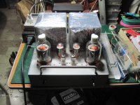
Hi George.... saw image of your test board with the 4D32 transmitter tube and have rekindle my desire to build a SE 4D32 amp using Noguchi FM-24WS-3K5 OPT. Driver tube will be twin trioded 6EM7, and operating 4D32 with 400v plate @100mA. It's a Japanese circuitry.
Question is, what'll be the best driver tube for better sounding?
BTW, this 4D32 is intimidating, cheap, and looks like the fat bomb that was dropped over Japan !
!
Thanks!
Regards, Zekk.
Question is, what'll be the best driver tube for better sounding?
BTW, this 4D32 is intimidating, cheap, and looks like the fat bomb that was dropped over Japan
!Thanks!
Regards, Zekk.
Ehi Zekk, is the 4D32 available in singapore and how much is the going rate?
i am building one right now....driven by 6gf5 triode wired and 6dt8....
Hello Sir.... Bought 3 pcs. @ $75. + $16. shipping from US.
Looks mucho and could probably last another 20 years like me
.Breadboarded this single-ended 6EM7 > Telefunken EL 51, sounds promising!
Next , I'll try out the 4D32.
I'm not a EE, but just an old copycat, seeking reliable schematic to ponder on! U've any to share?
Thanks!
Question is, what'll be the best driver tube for better sounding?
That question has been asked ever since people started making amps. Unfortunately it is impossible to answer......It's like what is the best car, a BMW or a Honda? Most people would choose the BMW, but I'll keep my old Honda Element since I haul more junk than people.
I used the 6EM7 as a driver tube when I made a cathode follower amp since I needed a lot of output voltage swing. It worked fairly well, and sounded good in that case. I did find quite a big variation in the gain of the first stage. I had to go through several tubes before finding two that had the same gain.
Bought 3 pcs. @ $75. + $16. shipping from US
I bought 6 pieces from an Ebay seller several years ago. They were still sealed in the original cartons, but upon opening two were obviously gassy. One had no getter, the other had a faint white spot. The seller replaced them. Apparently that's a common problem with these tubes.
^fwiw, i bought two quads of those from surplus sales of nebraska years ago when they had a sale for $19 each, they all were good tubes, no issues.....they were all in big cartons....
U've any to share?
Attachments
Hello Everyone,
My question, to get the gain in check, I can either put a voltage divider at the signal input of the amp, or I could try to implement some global negative feedback. If I were to try feedback, where would I inject the signal? I am a little confused with this as the DC offset circuit at the grid of the second triode in the first stage adds to the complexity.
You could get rid of the DC offset problem by half capacitor coupling (attached). This isolates one side of the input LTP, ensuring that the grids of the second LTP are both at the same DC potential. This takes care of the DC offset, and since the drivers are also capacitor coupled, it's not a problem.
This frees up the second half of the 1st LTP to act as a gNFB summing node. You can also keep the pot, and make the gNFB variable.
Attachments
Anyone look at these Mosfets as followers? Zener protected gates built in. Sub 1pf Crss above 30V, with a slightly rising characteristic.
http://www.infineon.com/dgdl/Infine...N.pdf?fileId=5546d46255a50e820155d90b3461516c
http://www.infineon.com/dgdl/Infine...N.pdf?fileId=5546d46255a50e820155d90b3461516c
Anyone look at these Mosfets as followers? Zener protected gates built in. Sub 1pf Crss above 30V, with a slightly rising characteristic.
http://www.infineon.com/dgdl/Infine...N.pdf?fileId=5546d46255a50e820155d90b3461516c
Looks pretty nice. The one thing I see is that it isn't rated for a lot of power. As long as you don't stuff it into a sealed box and make it dissipate 15W or something, it looks like a very good part.
At first, the rising slope of Crss looks like it might be a defect, but I think it is a good thing. Most people like Crss to stay flat to avoid the possibility of significant PIM distortion. However, PIM distortion can be caused by both nonlinear capacitances at the input of a stage *and* non-constant rp of the driving stage. Most (all?) tubes have falling rp as plate voltage goes up.
If you have gently rising Crss in a follower, that would compliment the falling rp and produce a more constant product of R and C. As driver plate rises (and driver rp goes up), Vds of the follower goes down (and Crss goes down, as long as you keep it above 30V or so).
However, my gut is telling me that this won't matter much since the capacitances are so small that driving impedance would probably have to be really high to have much phase shift at audio frequencies. Probably not much practical improvement but it might appeal to perfectionists.
Cool, a MOSFET with second breakdown like bipolar transistorsAnyone look at these Mosfets as followers? Zener protected gates built in. Sub 1pf Crss above 30V, with a slightly rising characteristic.
http://www.infineon.com/dgdl/Infine...N.pdf?fileId=5546d46255a50e820155d90b3461516c
(see diagrams 2 and 3)Is not linearly following the max. dissipation like normal MOSFETs at DC
Probably because it is a SJ (super junction) device, so dense that produces hotspots
Anyway, a good candidate for some followers.
Question: I've been looking at this thread for a while now and I'd really like to try something like it in the no too distant future.
Regarding the SS followers, is there any reason we couldn't use a current mirror and a CCS to potentially eliminate one of the adjustment pots for the bias? My thinking is that as long as the resistor loads are well-matched that it might make setting the output tube negative bias a bit easier.
Regarding the SS followers, is there any reason we couldn't use a current mirror and a CCS to potentially eliminate one of the adjustment pots for the bias? My thinking is that as long as the resistor loads are well-matched that it might make setting the output tube negative bias a bit easier.
So here's kind of what I was thinking:

I'm green wrt SS but have a couple of Douglas Self books. I'm thinking that setting the current in the CCS (shown right) will also set the emitter voltage in the followers (which sets the grid voltage of the output tubes). The current mirrors will present a nice high impedance load for the followers as well.
My goal here is just to eliminate some of the trim pot bias adjustments, though I realize I've multiplied the number of transistors tenfold. Haha.
I made myself a bias servo board to solve this problem. Every amp that I build has a cheap AC to +-15V brick that powers as many servo channels as I want to add. I can set the bias for my power tubes with one reference voltage adjustment that I set once in the lifetime of the amp. Bias stays correct through all tube changes, tube aging ect. I just used the circuit published in Menno Van Der Veen's "High End Valve Amplifiers 2."
- Status
- This old topic is closed. If you want to reopen this topic, contact a moderator using the "Report Post" button.
- Home
- Amplifiers
- Tubes / Valves
- 6L6GC AB2 Amp