From personal experience, and in PP, the DHT's seem to yield something magical, especially 2A3's and 45's (I don't like 300B's as much). I don't know what it is. I thought it was that these tubes are capable of very low distortion output when in a reasonably well designed circuit, lower distortion than triode-wired EL34 or 6L6GC, or even triode-wired 6V6GT or EL84. Am I just plain wrong about that?
Yes, you are. As I mentioned a few posts back, compare the distortion of PP 300B to PP KT88. And when you take into account the driver requirements, the comparison tilts further in the direction of more modern tubes. Now, if there's something in the distortion/microphonics/esthetics/what-have-you of DHTs that cause you to prefer them, chacun a son gout. But for the objective standard of distortion, DHTs don't bring anything special to the table.
Before you ask, yes, I've built and owned DHT amps. I don't bother anymore.
...I've built and owned DHT amps. I don't bother anymore.
")
The bargain-hunting cheapskate in me is very happy to hear that. 2A3's were cheap back when nobody loved them, but now they're crazy expensive. And let's not even mention 300B's (ay yi yi).
I have a good sized stash of 1980's Philips/ECG 6LGGC at my disposal. Looks like I have no more excuses. I'll just have to build a PP 6L6GC-triode or UL amp with best quality parts and challenge my friend's PP 300B amp to a duel.
--
Should this be a different thread? Or is this an ages-old subject that I'm just dredging up again for the umpteenth time?
It's an ages old subject that won't be answered here or in any other thread in the near future here. There has been much fact, superstition, opinion, and plain old BS thrown on this subject that it would be pointless to throw some more here, but here are my observations on the subject.
2A3's were cheap back when nobody loved them, but now they're crazy expensive. And let's not even mention 300B's (ay yi yi).
I collected some used 45's and used RCA 2A3's for under $10 each back then. I also got some Chinese and Russian 300B's, 211's and 845's when they were $25 each.
About 10 years ago I built a push pull 300B amp using an early version of my twin LTP circuit using junk quality parts. It sounded so nice that it is the only amp I built in that era that I still have.
Bottom line: I do not expect an audible difference in sound.
I have tested my breadboard with 45's in it making about 15 WPC (AB2) and the EXACT SAME circuit and OPT's with trioded KT88's. Granted the power supply was 325 volts with the 45's and 450 volts with the KT88's. There was a very noticible difference in sound. Was the difference due to the extra headroom provided by the KT88's and the higher supply voltage? I don't know but I liked both a lot. I did not try 300B's at the time, but they will be tested eventually.
At the time I built this amp I was under the belief that a triode or a triode wired pentode with zero feedback provided the best sound. Then I spent a year long diversion with Pete Milletts DCPP amp and learned that a pentode with just enough Schade feedback to kill the "pentodeness" sounds very good for dynamic music. I have also built two pairs of high efficiency horn speakers, so it's time to revisit it all.
The bottom line is that what sounds the best to you depends on the speakers, the type of music you play and how loud you play it. The best amp for Diana Krall or Loreena McKennitt at a reasonable level is not the best amp for Metallica cranked to 11. I like both types of music, but I have yet to find one amp that works right with both.....but I keep looking.
Johan, not at all out of turn. Perfectly relevant.
I may have been unclear. By A and B, I didn't mean classes of operation, I was referring to two different ways of setting up an output stage. I should have used X and Y.
Why would you exclude plate-to-grid feedback via a resistor (e.g., Schade) but include plate-to-grid feedback via a transformer (e.g., ultralinear)?
Good point as usual.
But I think one should be careful to equate 'outside' feedback, in this case shunt (Schade), to internal feedback. Point is that usual shunt feedback or any other type round a tube, will decrease distortion but not the 'internal characteristics' of the tube. A pentode will still have pentode characteristics. No amount of any feedback will change that to triode characterisitcs. (The distinction of using the words 'external' and 'internal' is descriptive rather than matematically accurate - basically in UL the term 'outside feedback' also applies.)
But in UL (I prefer 'distributed load') the operation of the tube itself is changed, just as much as if the arrangement was due to some funny internal electrode arrangement (which in a sense it is!). Let us not forget that a pentode in a UL topology, is a pentode with 0% G2-tapping but triode with 100% G2-tapping. Somewhere in-between one can get almost triode rp and distortion characteristics, while retaining near pentode efficiency and sensitivity etc. etc.
As Prof. Otala indicated in his classic article on the effect of the output active device's internal characterisitcs on output performance, which is not changed by NFB, a pentode stage with NFB will not give the same performance as a (in this instance) pentode 'triodised' by UL. The latter is preferable.
I don't know what it is. I thought it was that these tubes are capable of very low distortion output when in a reasonably well designed circuit, lower distortion than triode-wired EL34 or 6L6GC, or even triode-wired 6V6GT or EL84. Am I just plain wrong about that?
--
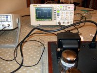
This chart is from triode-wired push pull KT88s in a 14dB feedback amp that I once made. The output level is low, near 1W, not to fry the audio PC card. Has higher 2nd than 3rd although symmetrical output, but that maybe comes from the drivers mainly, and/or output stage imbalances.
Attachments
Has higher 2nd than 3rd although symmetrical output, but that maybe comes from the drivers mainly, and/or output stage imbalances.
The amp designed here is fully symmetrical from input to output. In theory it should have near zero 2nd harmonic output. Surprise...Mine has higher 2H than 3H for most operating conditions.
It is common belief that push pull amplifiers cancel all the second harmonic generated in the push pull stages. This is only true if everything is perfectly balanced for every operating condition. What are the chances of finding a pair of output tubes that have exactly matched Gm over the entire current range that will be seen in the amp? What are the chances that they will stay matched after a few months? Is your OPT perfectly balanced from one side to the other for all audio frequencies?
It has been my experience that the 2H can be minimized at one frequency and power level. it will creep up as you deviate from the conditions that it was adjusted for.
I find that amps (especially big amps) often sound better at low volume levels if the output stage is a bit off balance. This may be due to the ears preference for some 2H or it may be due to moving the transition through the OPT's dead zone out of the low power listening area (the "First Watt" phenomenon).
Here is another unexplained phenomenon. Put a load resistor on a big tube amp. Crank it to a fairly high power level with a constant tone (1 KHz works). Most OPT's will emit some sound. Tweak the output tube DC balance. You will hear a point where the OPT "singing" is minimized. This point will be at a DC imbalance, but tends to sound better than a perfectly balanced amp.
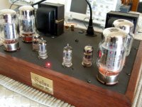
All you mention above is wise. Bias imbalance should be ''de-tuning'' the mechanical resonances of the output transformer's halves also. Some analogue ''dither'' maybe a delight, rather natural to accept. That one in the following pics was the amp BTW. Has non symmetrical paralleled sections 1st stage, and BJT cascode cathode side CCSed splitter. 235kHz bandwidth at 1W.
Attachments
Guys,
I got half way thru' this thread and decided to leap to the end with a suggestion. Appologies if its been made before.
The 10K 5W resistors used as loads on the source followers can be easily replaced with current sources. Using current source loads on the source followers brings 2 benefits, 1st the source followers themeselves will have less distortion BUT mostly the high AC impedance of current sources isolates any B- power supply noise. The first time I tried replacing source follower resistor loads with current source loads on one of my BH Amps I could scarcely believe the sonic improvements. Big powerful sound, masterfull control and an absolutely "black" background revealing fine detail that I simply had'nt noticed before as it was masked by low level broadband noise, either grid noise or negative supply noise or perhaps some of each.
Anyway - something to try if you want. I found you did'nt need the most "super" current sources, "Ring of Two" transistor current sources worked just fine.
Cheers,
Ian
Salas,
Sorry, No - I can do FFTs with my digital CRO but with an 8 bit front end its doesn't tell you much, just doesn't have the resolution of a good sound card (which I don't have).
In the listening room the result was VERY noticable, particularly as songs fade out at the end, you noticed another second or two of music which was previously masked by noise. Noise which I had'nt really noiticed was there until it was gone.
It made such an improvement to my power amps that I had to start a relook at my sources and preamp. The usual "round we go again", fix warts in one area and it reveals the warts somewhere else.
I'm happy that your friend enjoyed the Baby Huey. The reason I was wading thru' this thread was to "cherry pick" ideas for a BH successor.
Cheers,
Ian
Last edited:
I used regulated -V for the splitter's cathode CCS and the that amp is quiet as a mouse on >100dB horn speakers even. Although AC heated all over. -100dB 50Hz hum as you saw on its FFT. But I don't use MOSFET followers, just small coupling caps to avoid long sticking. So yes, PSRR from active loading, or regulation, pays in selected areas.
Salas,
Ians wild assertion for the day - what is wrong with 90+% of tube amps out there is inadequate control of output tube control grids, usually too high a value of Rg1 so that grid noise is not properly shunted to signal ground and wimpy drivers.
I now routinely use direct coupled, current source loaded, source followers to drive output tubes, bias applied to the MOSFTET gate. HiFi Amps, Guitar Amps, SE or PP - they all get the same treatment, why? coz I haven't found anything better yet.
Woops - lunch hours over - back to the day job design (laser receiver photomultiplier circuits today).
Cheers,
Ian
Yes, its a good scheme. Gives slam and drops noise. When those areas are needy, which happens in many designs. I assist tubes with semis wherever positive too, no purism here. That one had good grip and very low noise so I did not add such buffers, just cascode for cathode and -V regulator for it.
Thanks Gingertube,
I remember that there was a similar thread running parallel with this one something like 'Mullard style KT88 mono blocks' (?). I think on that amp the MOSFET followers had CCS. Tubelab was the inspiration/mentor/tutor for this amp. I believe at some point he said he tried CCS on the source followers, but could not hear a difference. I notice too that the new 'BOOK' (MG Valve Amplifiers 4th Edn) has powerdrive style MOSFET followers with a CCS.
It should be easy to implement, so I might give it a try, either 'ring of two' or I have a few 10M45s on hand.
Cheers,
Chris
But I think one should be careful to equate 'outside' feedback, in this case shunt (Schade), to internal feedback. Point is that usual shunt feedback or any other type round a tube, will decrease distortion but not the 'internal characteristics' of the tube.
Not statically, it won't. As for the rest, my expert disagrees with your expert
 (WHUDDA SURPRISE! )
Thus the quality improvement due to internal
feedback is of the same nature as the quality
improvement due to external feedback. This line of
thought pertaining to negative feedback might be
useful in comparing the inferior frequency response
of a pentode to the frequency response of a triode.
Inherent Feedback in Triodes
H. Stockman; Wireless Engineer; April, 1953
Here, he's telling us that it doesn't make any difference: "internal" feedback or not. As for "UL" v. "Schade", it doesn't make a bit of difference. The former simply inserts that NFB into a less sensitive grid than the latter. Nothing "magical" about UL, it's still lNFB regardless of what you call it.
The only reason I prefer UL is that it keeps designers from using types like HD-TV finals that run their screens at voltages way below the plate voltage.
Other than that, I'm not one to just throw in some value of lNFB just because it's there. I prefer listening while running a new design open loop for at least a week before deciding on what corrections are needed. 807s sure did need the extra help provided by lNFB, but 6BQ6s sounded pretty good so's not to need it -- just enough gNFB to take off the "edge", and improve woofer damping. (6BQ6s sound every bit as good as the famous 6V6-oids, but with Mowatts.)
I got half way thru' this thread and decided to leap to the end with a suggestion. Appologies if its been made before.
Good suggestion....is it a new idea? In my mind the best possible incarnation of the cathode follower was invented and patented by Ross MacDonald in 1955. It not only has a CCS in the cathode, it has a bootstrapped follower on the plate so that the active follower sees a constant current and a constant plate to cathode voltage. Some versions even use a feedback loop. I decided that the design was good enough for an output stage, so I built a 20 watt version. It works very well. See this thread for theory:
http://www.diyaudio.com/forums/tube...wer.html?highlight=augmented+cathode+follower
The work by MacDonald was done to compensate for the shortcommings of the devices available in 1955. A tube follower is not perfect and does not have a constant gain (loss) across its output voltage swing. It has a significant internal resistance. These are both manifestations of a medium Gm value.
The mosfet has a much higher Gm than any tube and makes a much better follower. The mosfet has near perfect follower characteristics and a very low internal resistance, so external assistance provides less benefit than a tube follower. It is still not perfect and can benefit from a CCS in the source. It can also benefit from a bootstrapped drain supply too.
ANY device, but particularly semiconductors, will exhibit a voltage variable capacitance effect. This change in capacitance with a change in applied voltage can cause PIM, Phase InterModulation distortion. PIM is not easilly measured in small quantities, but it seems to be one of the reasons the old school still doesn't want sand in the signal path. The bootstrapped drain supply will remove this effect.
Allen Wright's SLCF is a direct descendant of MacDonalds patented CF without the feedback loop. The exact same circuit can be built with mosfets (including the feedback if desired). I have tried it and found zero to barely noticible audible improvements. It may show better improvements in noisier applications.
Ians wild assertion for the day - what is wrong with 90+% of tube amps out there is inadequate control of output tube control grids
BINGO! This was my belief back when I proposed the PowerDrive several years ago. When I first stated this on my web site the email was 99% negative. Some even suggested changing my name to Transistorlab! A few forward thinkers actually tried it and several years later...
I notice too that the new 'BOOK' (MG Valve Amplifiers 4th Edn) has powerdrive style MOSFET followers with a CCS.
Morgan contacted me about including PowerDrive in the 4th edition, but due to some kind of publishing problem we still can not buy this book in the US. I haven't seen it.
Morgan contacted me about including PowerDrive in the 4th edition, but due to some kind of publishing problem we still can not buy this book in the US. I haven't seen it.
Soon, very soon. Just finishing up writing a review for the next Linear Audio.
I think it won't give up much to say that when I was visiting him a few years ago, we got into an argument over whether a MOSFET source follower or a high gm tube cathode follower would show less distortion. He felt that at the currents used for the followers, the MOSFET's gm might end up lower than the tube's, and that the distortion under load would be higher. We agreed to go upstairs to the lab and set up the experiment, with a little side bet (one of his CV1988 versus one of my red base 5692). The data from that experiment is in VA4, and I have a nice CV1988.
Mosfet Voltage variable capacitance effect - I looked at this from a purely theoretical point of view. Check out the device capacitance graphs on any mosfet datasheet (Crss in particulqar). So long as you maintain a minimum of say 20 to 25 volts from Drain to Source at the positive going signal peak (at the drain) then this effect is minimal. I decided that bootstrapping the mosfet drain was probably not going to help a lot. Having said that I haven't actually tried it (bootstrap of the drain) and listened to the result, that after all should be our final and deciding test.
Cheers,
Ian
Cheers,
Ian
Miles,
Point taken. Throwing myself wide open to criticism, is it then that UL can be seen as some form of 'non-linear' feedback, compared to the usual parallel type, thus creating the UL characterisitc?D - there, now that is a profound piece of logic!)
I am simply saying that what difference there is for me, is in the fact that parallel (Schade) feedback still leaves one with an intrinsic pentode, whereas UL leaves one with mainly triode characteristics - through whatever kind of feedback influence. I am also careful with claiming that one type is superior to the other, though to me it would appear to be. A lot depends on the rest of the topology. [I will have to get back to the Otala article (written for transistor output topologies, a few decades ago) to recall the details of his point that an intrinsic low impedance output topology before feedback is to be preferred.]
Point taken. Throwing myself wide open to criticism, is it then that UL can be seen as some form of 'non-linear' feedback, compared to the usual parallel type, thus creating the UL characterisitc?
D - there, now that is a profound piece of logic!)I am simply saying that what difference there is for me, is in the fact that parallel (Schade) feedback still leaves one with an intrinsic pentode, whereas UL leaves one with mainly triode characteristics - through whatever kind of feedback influence. I am also careful with claiming that one type is superior to the other, though to me it would appear to be. A lot depends on the rest of the topology. [I will have to get back to the Otala article (written for transistor output topologies, a few decades ago) to recall the details of his point that an intrinsic low impedance output topology before feedback is to be preferred.]
- Status
- This old topic is closed. If you want to reopen this topic, contact a moderator using the "Report Post" button.
- Home
- Amplifiers
- Tubes / Valves
- 6L6GC AB2 Amp