Well, guitvinny, you need to decide how much current would be best for the triode and circuit you're using. This is dependent upon the tube type, its plate curves and the load line you select. As a guide, in a long tail pair splitter these would be in the order of:But how I calculate the current that need to be draw for the triode ?
6SL7 : 120k load, 0.75mA plate current
12AX7 : 120k load, 0.75mA plate current
12AT7 : 47k load, 2mA plate current
12AU7 : 33k load, 3mA plate current
6SN7 : 33k load, 3mA plate current
Since the CCS is supplying current for two triodes in the LTP, it needs to supply twice the current shown above.
Hi quitvinny ,
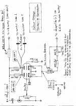
I have done some experiments with the input stage of your amp
following the original schematics , and I could find some opera-
tion failures , then I made some corrections and make a new
schematics , where you can see the changes and the “tips”
for a correct Class A operation .
There are some critical points , as follows :
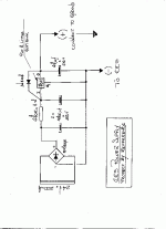
a) The CCS power supply , needs to be very , very , very well
filtered , to do not introduce “hummmmm..”
b) The grid bias voltage of 12AT7 ( determined by the cathode
voltage against the ground ) is very , very , very critical , and
needs to measure EXACTLY 1.00 Volt + or – 2%
c) The current sensor ( R6 = 75 ohms ) , is a very,very critical
value , and can not be fixed , because it depends of various
parameters like 12AT7 tube brand , LM317 brand , tube’s
life expectancy , etc. , then I put a trim pot in the place of a
fixed value resistor , so you can adjust the grid bias voltage .
d ) I have substituted the R 3 and R 4 resistor by an easier
to find 15 K x 3 W , metal film resistors .
e) The voltage value measured in the 12AT7’s plates , the
pins 1 and 6 is very critical and must stay between 180 and
190 Volts , in both plates , do not needs to be exactly the
same value at both plates .
f) If the +B power supply schematics that I had sent , can
mantain the voltage at 290 – 300 Volts after you have
CONNECTED ALL STAGES OF TWO CHANNELS ,
GREAT it’s OK !! You will not need the resistor and
capacitor in dotted lines .
If the +B value is higher than 290-300 V , you will need to
lower it , using the resistor and capacitor in dotted lines .
If the +B value is lower than 290-300 V , you will need to
rise it , changing the value of power supply’s resistors
( both two ) from 270 R x 20 W to 220 R x 20 W .
It’s unpredictable , because it depends only of the power
tranny characteristics . ( winding resistance , magnetic flux,
regulation , etc. )
To adjust , do the follows ,
1 – Adjust the trim pot , to measure 1.00 volt at the cathodes
against the ground.
2 – Measure the plates voltage , and if it’s OK , according
to item e ) above , END of adjustment and enjoy the sound !!!
3 - If not , verify the +B voltage , and proceed according to
item f) above .
3 – Adjust the trim pot again , and measure the plates voltage
again .
4 – You need to re-do this procedure until all values are OK !!
All correct values are indicated on the schematics . And if
you can get all of them , the SOUND IS VERY NICE .
With good Bass response and detailed Treble , the Midle
are very , very nice too !!!!
No need to worry , the procedure looks like very difficult
but IT IS NOT , it’s easier than you are thinking !!!
Now you have TWO options of CCS . Choose anyone
you want . Any doubt , feel free to ask .
Good luck ,
Carlos
P.S. I’m formating the CCS power supply schematics and
Input Stage New Design , to fit the site’s parameters .
I’ll send it A.S.A.P. Wait !!!
Wow, that`s a breath of life for this project !
Me too I draw few load line and use the -1V grid bias.. For now, I have order the metal work from a freind and I redraw the whole thing (you will see it soon). I found this project so interesting ! I learn alot about tube ! that`s awsome !
Simple question, wire wound resistor in cement (ebay item : 3816944102) is good as wire wound without case.. right ?
Me too I draw few load line and use the -1V grid bias.. For now, I have order the metal work from a freind and I redraw the whole thing (you will see it soon). I found this project so interesting ! I learn alot about tube !
Simple question, wire wound resistor in cement (ebay item : 3816944102) is good as wire wound without case.. right ?
There we go, I redraw the whole beast
(If you don`t see it, again, just go to webshots.com and search for guitvinny in community, this pic is call PP6l6 final.jpg)
This week I will order my 3 edcor transformer, so if you see something wrong with the power supply, tell me. Power tranny will be : 120v primary, 270-0-270 @ 450mA, 15V @ 600mA, 6.3V @ 4 A. The output transformers will be 2 edcor CXPP25-8-5K (25W, 8 ohm, 5000 ohm).
Thank you all for your help, if you have physic building tips (like, should I ground the input, the volume pot, twist filaments wires.. etc.)
An externally hosted image should be here but it was not working when we last tested it.
(If you don`t see it, again, just go to webshots.com and search for guitvinny in community, this pic is call PP6l6 final.jpg)
This week I will order my 3 edcor transformer, so if you see something wrong with the power supply, tell me. Power tranny will be : 120v primary, 270-0-270 @ 450mA, 15V @ 600mA, 6.3V @ 4 A. The output transformers will be 2 edcor CXPP25-8-5K (25W, 8 ohm, 5000 ohm).
Thank you all for your help, if you have physic building tips (like, should I ground the input, the volume pot, twist filaments wires.. etc.)
Hi quitvinny ,
Yes , it’s for one tube 12AT7 , only one channel .
You have to do it twice ( left channel and right channel ) .
No needs to have a 400 mA power tranny , 200 mA is
enough for BOTH channels , BUT you have to do 2 power
supplies ( 2 bridge rectifiers , 2 set of filtering caps , 2 x 7812,
etc. ) and connect both on the same power tranny ( 24 V x
200 mA ) . This way you will have a perfect channel separa-
tion .
Regards ,
Carlos
- Status
- This old topic is closed. If you want to reopen this topic, contact a moderator using the "Report Post" button.
- Home
- Amplifiers
- Tubes / Valves
- 6L6 Push pull -- Power tranny question

