Yes, Carlos, you're right. Most guitar amps use pentode mode (and this may be the best direction for guitvinny to take). Johan's suggestion as to why pentode mode is better for guitar amps makes sense: low damping factors and plenty of bass boom in the speakers.I have to recognize that pentode operation ( IN THIS CASE ), sounds better . Don’t ask me why !!
There are many of examples of Marshall and Fender pentode amp schematics available on the web. I notice that they didn't worry too much about regulating the voltage for the screens; that certainly helps to keep the design simple.
Hi quitvinny ,
Hi Potqieter , thanks for your reply . Good if you agree with bias by a cathode resistor . At my turn , I agree entirely , that quitvinny have to use a large by-pass capacitor ( may be 2200 or 4700 uf x 35 Volts ).
About the power transformer rating , I agree again , quitvinny can use
one ( or two ) that can deliver 200 mA per channel [ the quiescent current is 160 mA per channel at 300 V + B ( I plate + I screen )] .
Your explanation about my perception makes all sense .
Hi ray_moth , thanks for your reply .You are right too . The great majority of amp builders , don’t worry to use stabilized supply for the screen grids , but that would be the best . May be to simplify the design and lower the final cost .
Quitvinny , now it is your turn . After all discussion about your amp ,all
of us want to know if remained any doubt in your mind .
If not . Good !!! Start to build it !!!
If yes , please feel free , to ask anything you want !!!
Regards for all ,
Carlos
Thank for all your input !! That`s great !
I talk with edcor guys, they can make me a power transformer that can supply both channel for realy good price (270-0-270 @ 450mA, 6.3 V @ 6A, 12V @ 1A all this for 59.41 ! ) so I`ll go with this plus they can make me two 25W 5000 to 8 ohm output tranny, for a total of 147.31 $ for thoses 3 tranny.
For the shematic, i think I will stick with the orignial desing, except for the CCS, so that would be great if you can help me with this part, I will use the 12AT7, as the schematic say. I understand the concept of baby huey CCS but not how to calculate it, and will I use the 12 V line on my power tranny ?.
To splitt my single tranny for both channel, can I just do a ``Y`` at the red spot on the pic ?
For the filtering a single 450mA, would the capacitor value will change ? I dont want to use a choke... only RC. Except if you tell me that will be ALOT better.For the rectification, I heard 4007 is a quite slow diode, so with what can remplace it ?.. that will support this current..
Last thing ! : Can some one make me a summary of every suggestion that was made in this forum... There is so many ! I know I said that I stick with original schematic.. but we never know I`m in the gatering stage now.
And Thank you all ! this community is full of useful information !
I talk with edcor guys, they can make me a power transformer that can supply both channel for realy good price (270-0-270 @ 450mA, 6.3 V @ 6A, 12V @ 1A all this for 59.41 !
) so I`ll go with this plus they can make me two 25W 5000 to 8 ohm output tranny, for a total of 147.31 $ for thoses 3 tranny. For the shematic, i think I will stick with the orignial desing, except for the CCS, so that would be great if you can help me with this part, I will use the 12AT7, as the schematic say. I understand the concept of baby huey CCS but not how to calculate it, and will I use the 12 V line on my power tranny ?.
To splitt my single tranny for both channel, can I just do a ``Y`` at the red spot on the pic ?
For the filtering a single 450mA, would the capacitor value will change ? I dont want to use a choke... only RC. Except if you tell me that will be ALOT better.For the rectification, I heard 4007 is a quite slow diode, so with what can remplace it ?.. that will support this current..
Last thing ! : Can some one make me a summary of every suggestion that was made in this forum... There is so many ! I know I said that I stick with original schematic.. but we never know
I`m in the gatering stage now.And Thank you all ! this community is full of useful information !
An externally hosted image should be here but it was not working when we last tested it.
Hi quitvinny ,
About the output tranformer characteristics , please see the item 2 of my suggestion # 2 , on my post # 12 . If you want pentode operation , just ignore the screen grids taps , and isolate them . If not ( UL operation ), just follow the original schematics .
As Potqieter suggested , you can change the cathode by-pass cap ( 470 uf x
50 V ) , to a large value ( we can say 2200 uf x 35 V ) .
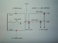
The 1N4007 will not support the “in rush” current at high voltage , so I did a simple drawing , of a very useful power supply , adequate to feed the two channels . You can improve it with 0.1 uf x 630 V MKT or MKP caps paralleled
with electrolytic caps and each one of 1N5408 diodes .
About the heaters , the output stage will be feed with 6.3 VAC winding.
I strongly suggest to you that you order a power transformer with a 15 Volts x
1 A winding , because you can rectify them with a bridge rectifier ( do not connect the bridge’s negative side to the ground , ) and filter with a 4700 uf x 25 V elec. cap and then apply to 3-terminals regulator , like 7812 or LM 317T , so you can feed the INPUT STAGES Heaters , with 12 V DC ( lower the humm !! ) . If you will use the 12AT7 tube , feed 12 VDC into pins 4 and 5 and connect the pin 9 to the ground and VERY IMPORTANT !!! : the pin 9 of both input tubes will be the only point (s) where the heater circuit makes contact with ground .
Because I only like to build and sell amplifiers , built according “ the old fashion
way” , I have not much experience with the behavior of CCS into tube circuits ,
( regarding the sound quality and tonal richness ) , so I suggest that you ask for
help with Ray_Moth or with Potqieter ) , in any case don’t use the LM 317 T ( as
Ray_Moth said previously ) , you must to use low-noise discrete transistors , configured like a CCS classical circuit , and metal-film or wire-wound resistors
( if possible )
Feel free to ask again if you need ,
Regards ,
Carlos
About the output tranformer characteristics , please see the item 2 of my suggestion # 2 , on my post # 12 . If you want pentode operation , just ignore the screen grids taps , and isolate them . If not ( UL operation ), just follow the original schematics .
As Potqieter suggested , you can change the cathode by-pass cap ( 470 uf x
50 V ) , to a large value ( we can say 2200 uf x 35 V ) .
The 1N4007 will not support the “in rush” current at high voltage , so I did a simple drawing , of a very useful power supply , adequate to feed the two channels . You can improve it with 0.1 uf x 630 V MKT or MKP caps paralleled
with electrolytic caps and each one of 1N5408 diodes .
About the heaters , the output stage will be feed with 6.3 VAC winding.
I strongly suggest to you that you order a power transformer with a 15 Volts x
1 A winding , because you can rectify them with a bridge rectifier ( do not connect the bridge’s negative side to the ground , ) and filter with a 4700 uf x 25 V elec. cap and then apply to 3-terminals regulator , like 7812 or LM 317T , so you can feed the INPUT STAGES Heaters , with 12 V DC ( lower the humm !! ) . If you will use the 12AT7 tube , feed 12 VDC into pins 4 and 5 and connect the pin 9 to the ground and VERY IMPORTANT !!! : the pin 9 of both input tubes will be the only point (s) where the heater circuit makes contact with ground .
Because I only like to build and sell amplifiers , built according “ the old fashion
way” , I have not much experience with the behavior of CCS into tube circuits ,
( regarding the sound quality and tonal richness ) , so I suggest that you ask for
help with Ray_Moth or with Potqieter ) , in any case don’t use the LM 317 T ( as
Ray_Moth said previously ) , you must to use low-noise discrete transistors , configured like a CCS classical circuit , and metal-film or wire-wound resistors
( if possible )
Feel free to ask again if you need ,
Regards ,
Carlos
Little quick question, does the quality of the capacitor in the power supply affect the sound of the amplifier, because I can easly get cap (470uf x 450V) with mouser, but its like xicon or something like that...
Next, resistor with no power rating indicated, it`s 1W i guess ?
Right now I`m in the redraw-everything-with-your-sugestion stage, I will have some news soon annnd question soon !
Thank !
Next, resistor with no power rating indicated, it`s 1W i guess ?
Right now I`m in the redraw-everything-with-your-sugestion stage, I will have some news soon annnd question soon !
Thank !
My comment is that many people claim to "hear" a difference with different power supply capacitors, but blind tests often contradict this.
The most important point is that the first capacitor must be able to withstand the ripple current. This can be a difficulty because it is usually unknown; it depends on the resistance (impedance) of the power transformer winding. Further, I really had to hunt here to find ripple specs at all for electrolytic caps - I could only find data for Hitano. This helps you little, except to say do not use the first physically small cap that you can get. Electrolytic caps with sufficient ripple capability are larger than normal ones - sorry I cannot be more specific.
Then the influence in audio (if any) usually comes at high frequency from the series inductance of such caps (they are constructed in a spiral wind). Again this can be difficult to measure, except that 2 smaller caps in parallel is often better than one large one - but this is more valid with transistor circuit requirements (thousands of uF). I have measured a JJ 100uF 450V to be 0,3 mH. This translates to 60 ohm at 30 KHz, which can maybe be a factor. So we put a polyester in parallel, because of its lower loss at high frequency. But I measured several such caps between 330nF and 1uF (all 630V) and not one had an internal inductance lower than 30 mH! It also varies, depending on the make.
Still, one mostly uses 0,22 - 0,47uF polyesters in parallel with the electrolytics, if only to feel better! (I am referring here to the power supply output caps; the ones at the amplifier side.)
I am sure others will comment. (And I do not see an unmarked resistor in Carlos' circuit.)
Regards.
Hi quitvinny ,
As I said in my post # 24 , you can improve the power supply’s quality ,
putting MKT or MKP caps , paralleled with electrolytic caps .
I suggested 0.1 uf x 630 V , and Potqieter suggested the same thing
but with values of 0.22 or 0.47 uf , as you can see our suggestions are
almost the same . You decide it !!
The power schematics that I sent , is very simple , it has 4 diodes , 3 electrolytic caps , 2 wire-wound resistors rated for 20 Watts and optional
choice : 2 or 3 MKT or MKP caps paralleled with electrolytics .
I do not know what another resistor are you talking about ???
Regarding your question about cap’s quality , see the Potqieter reply , I
agree entirely with him , when he went direct to the point , and said :
The first filter cap must be able to withstand the high ripple current !!
Please feel free to ask again ,
Regards ,
Carlos
Hi all !
I draw the near-final shematic of this amps :
I got few questions now :
- Can you help me fill the blue square ? (few resistor rating, fuse rating, CCS and amperes of 15 V loop)
- Please help with CCS !!!!!! And please check all this 15 V loop, I think I should use the LM150 to get 3 A of regulated current for the input fil. tube and for both CCS. 12,6 V @ 3A should be enough to run both CCS, no ?
- I wish to put a volume pot... dahhh , I know it`s better to put it after the input stage, but is there really a pot that can sustain those voltage ?? and be at the same time 4 level (2 per channel, one per tiode)... Or should I use a 2 level pot before the input channel ? If there other options tell me.
- I would like also a baxandal tone control does it worth it for the few composant I add to the signal chain, and where I put it in the circuit ?
And, again, thank you all, really, your help is precious !!
I draw the near-final shematic of this amps :
An externally hosted image should be here but it was not working when we last tested it.
I got few questions now :
- Can you help me fill the blue square ? (few resistor rating, fuse rating, CCS and amperes of 15 V loop)
- Please help with CCS !!!!!! And please check all this 15 V loop, I think I should use the LM150 to get 3 A of regulated current for the input fil. tube and for both CCS. 12,6 V @ 3A should be enough to run both CCS, no ?
- I wish to put a volume pot... dahhh
, I know it`s better to put it after the input stage, but is there really a pot that can sustain those voltage ?? and be at the same time 4 level (2 per channel, one per tiode)... Or should I use a 2 level pot before the input channel ? If there other options tell me.- I would like also a baxandal tone control does it worth it for the few composant I add to the signal chain, and where I put it in the circuit ?
And, again, thank you all, really, your help is precious !!
Go there : http://community.webshots.com/photo/550746705/2623379550068130724lzEcpf
If dosent work :
http://image63.webshots.com/163/3/79/55/2623379550068130724lzEcpf_fs.jpg
If its realy not working go to :
- webshots.com
- Community tumb
- Find a member : guitvinny
- Now you will see my 4 albums
- Go to audio amplifier
- And the sheamp picture is the one !
If dosent work :
http://image63.webshots.com/163/3/79/55/2623379550068130724lzEcpf_fs.jpg
If its realy not working go to :
- webshots.com
- Community tumb
- Find a member : guitvinny
- Now you will see my 4 albums
- Go to audio amplifier
- And the sheamp picture is the one !
Hi quitvinny ,
You did not understand , please see the suggestion on my
post # 24 , the input stage HEATER power supply , MUST BE
TOTTALY SEPARATED FROM THE REST , only to feed
the input stage ( of two channels ) HEATER circuit , because
this power supply , will be grounded in the pin 9 of each
tube , so it can not be used for another circuit . The secon-
dary winding ( 15 V @ 0.5 A or 1 A ) of power transformer
must be separated too . If you don’t have a separated
winding , you can use a little power transformer under
the chassis .
The CCS must be another power supply ( another secondary
winding too ) , with low current rating ( 100 mA is enough )
You can use the available secondary winding , or use a little
power transformer under the chassis .
The most important is : The heater power supply and the CCS
power supply must be totally separated one from another .
IN MY OPINION , the volume control should be located at the
amplifier’s input , so you can control the level of input signal ,
regarding doesn’t saturate the input stage . Pot’s and volume
control does not work well in circuits with DC , because DC
generates a LOT of noise when you rotate the pot’s shaft .
Regarding the Baxandall tone control , IN MY OPINION , you
will have to build it inside a preamplifier ( another assembly )
because it causes too much signal loss , and you will need
a new circuit of gain and a cathode-follower , to compensate
the loss and the impedance change . ( more tubes , more
current , heater supply , etc.,etc.)
About CCS circuit , I suggest that you ask for help to Ray_Moth
and / or Potqieter .
Regards ,
Carlos
P.S. I did not see the sites , yet . I'll see it after dinner
Just on tone controls:
A passive tone control causes an attenuation of a factor 10, while in the Baxandall the gain is 1 (one) but there's an extra stage, so it is all broadly similar; the extra stage is necessary anyway, other things being equal. The Baxandall has a very balanced boost and cut, the passive never quite.
One can make a Baxandall with gain (feedback taken from a tap on the anode load resistor) if one is short of gain, or for the full worth of the extra tube go a bit more complicated and use a twin triode with control feedback to the cathode of the first triode; that will really give some gain if required. Or to save, a twin triode one to each channel. (The Baxandall will work with a feedback factor of about 11; the rest can be used as gain.) Thus there are several options.
I am talking in general again, Quitvinny. If you want a specific circuit I will have to go back and read on your gain requirements, also I would not like to "publish" things that I have not hooked up and tested. That is comparatively easy but for a day or 2 right now I will not have time. State if you want that; in the meanwhile I am sure Ray_Moth or others are more than able to advise on a suitable CCS while I am occupied with less interesting matters.
Regards
Hi all, I think I got the right desing for the psu (http://image30.webshots.com/31/7/76/48/2784776480068130724tDHNFj_fs.jpg)
(if doesnt work see my last post for explanation where to go, except check the amp-psu. jpg image)
Please, do a little check out over it, should be good, but we never know...
For CCS, if you have reading over the internet where I can learn how to do it and calculate it... send it here
And, please can you help me with rating value that I miss (in blue in the last schematic I sent)
Last thing : does mylar capacitor is good enough to remplace MKT or MKP cap ?
Start to look like something ! Right now I`m around ebay for parts !
Hi quitvinny ,
I saw the previous schematics and everything looks like OK !!
BUT you need to revise the following :
1 – No necessity to use LM 150 ( rated for 3A ) , the “old and good” 7812 , with a good heat sink , will do the job .
2 – The power tranny winding , to feed the HEATER circuit ,
needs no more than 0.5 or 0.6 A ( If in the future you are planning to do a preamplifier , using the same power supply , then consider a rate of 1.5 A )
3 – The screen grid resistor must be rated for 2 Watts or more .
Wire-wound if possible , if not , use metal film 2 Watts
4 – All 1 K and 330 K resistors in the output stage , can be 0.25
or 0.33 or 0.50 Watts , preferably metal film , the 1K - 12AT7’s grids resistors can be 0.25 Watts metal film
5 – I strongly suggest that you increase the rating of output stage
cathode resistor , from 5 Watts to 10 Watts , you can use resistors
association ( series or parallel ) . And use ALWAYS wire-wound
resistor for this job .
6 – The CCS power supply , as I said , must be tottaly separated
from the rest and uniquely to feed the CCS , a rating of 100 mA
is more than enough , you can add a new secondary winding on the power tranny , or use a little tranny under the chassis .
7 – Add the level control at the input , and you can eliminate the
100 K resistor at the input , use a 100 K or 50 K log dual pot ,
a high quality one ( Noble , Alps , etc. )
8 – About the CCS , ask for help to Ray_Moth , send an e-mail
to him .
And I think that everything will be OK !!!
If you want that we see the modified project again , feel free !!
Regards ,
Carlos
P.S. MYLAR is the same of MKT cap , but MKP ( polypropilene ) , sounds better ( IN MY OPINION ) .
No need to send an email, I'll try to help here.8 – About the CCS , ask for help to Ray_Moth , send an e-mail
It's easier to discuss a simple, single NPN transistor CCS. This type of CCS works by comparing the base potential with the emitter potential (relative to the negative rail). Normally, there is a forward voltage drop of approximately 0.6 volts across the base-emitter junction of a silicon transistor. So, the voltage at the base must be 0.6v higher than the voltage at the emitter.
The collector-to-emitter current is controlled by having a zener diode on the base and a resistor in series with the emitter. Thus, the base voltage is fixed at the zener reference voltage w.r.t the neg rail. If the voltage across the emitter resistor is less than (the zener voltage - 0.6v), then the emitter-collector current will automatically rise to compensate. Similarly, if the voltage across the emitter resistor is more than (the zener voltage - 0.6v), then the emitter-collector current will automatically fall. In that way, the current remains relatively constant.
The required CCS current is set by calculating the value of the emitter resistor based upon the zener reference voltage. The value of the emitter resistor is calculated to be = (zener voltage - voltage between base and emitter)/required current.
For example, if you use a zener diode with reference voltage of 6.2v and you require the CCS current to be 2mA, then the emitter resistor should be set to (6.2-0.6)/.002 ohms = 2,800 ohms.
This arrangement works reasonably well in the tail of an LTP needing low current, such as a 6SL7; however, it's normal to use two transistors, giving more gain so that the CCS is more sensitive and, therefore, more constant.
Hi quitvinny ,
You can use ANYONE among them : LM 150 , LM 350 or 7812 .
LM 150 and LM 350 are the same , both rated for 3 Amperes ,
differing only at the temperature range . Both are variable too .
The 7812 has the same case ( TO220 ) , but it’s rated for 1.5
Ampere . Its output is fixed in 12 Volts .
As I said , if you are planning to build a PRE AMPLIFIER ( in
the future ) AND use the AMP’s power supply to feed it , THEN
is more convenient to use LM150 / LM 350 . If not , the 7812
will do the job . ( see the item 2 on my post # 36 ).
Re-do the schematics , and let us see it again .
Regards ,
Carlos
- Status
- This old topic is closed. If you want to reopen this topic, contact a moderator using the "Report Post" button.
- Home
- Amplifiers
- Tubes / Valves
- 6L6 Push pull -- Power tranny question