Another mystery is the addition of the small slots in the sides of the plate, usually for inspection of grid alignment.
The same plate structure is used in the 6BQ5, EL84, 6CW5, EL804 and 6HB6. One plate fits all the tubes, so they only have to make one stamping tool. Look at the GE "18 watt corporate plate" in all the 17 and 18 watt sweep tubes....all the same. In the later years of vacuum tube production it made it's way into some lower power sweep tubes too, like the 6BQ6GA and 6AV5GA.
Post #10
The schematic in post #10 is my design. For a hifi amp, it sounds great. I bought a bunch of 6HB6 green box GE's as well as a bunch of El Menco branded 6HB6/6HA6. They all seem to work well with the 6JN8 driver. There are several tubes that can be used for the driver, iike the 6GH8. Quite a few similar tubes can be used although different pinout. Nice sounding amp for hifi.
The schematic in post #10 is my design. For a hifi amp, it sounds great. I bought a bunch of 6HB6 green box GE's as well as a bunch of El Menco branded 6HB6/6HA6. They all seem to work well with the 6JN8 driver. There are several tubes that can be used for the driver, iike the 6GH8. Quite a few similar tubes can be used although different pinout. Nice sounding amp for hifi.
The schematic in post #10 is my design.
And, with minor changes, SY's (the RLD), Morgan Jones (the Bevois Valley) and mine (the SPP). In reality it is a pretty common circuit dating to the early 60's and probably before. Yes, it does work well.
The schematic in post #10 is my design. For a hifi amp, it sounds great.
How much watt's did you say
skal
How much watt's did you say
skal
About 9W RMS per channel.
Ok what output tx did you end up using , what range of bandwidth can it deliver,
what mods could i do to get about 15 watts.
cheers
skal
The model number for the OT is shown on that linked drawing. GXPP15-6-8K, Edcor.
The 6BQ5 datsheet says in class AB, at max plate and grid 2 voltage, you will get 17W. So if this tube is indeed a close match for the 6BQ5 maybe.
Or do what smoking-amp suggests.
You mentioned you had a 5K Ohm OT, and now need more Watts. Doubling up the 6HB6s could fill the bill.
Or using a bigger tube like 6GE5/12GE5/6JN6/12JN6/12GT5/6JZ6/12JT6
well i did mention that in my first post
skal
Well, if the 6BQ5 datasheet says it can do 17 Watts in class AB, then the 6HB6
(rated 10 W versus 12 W) should be able to do (10/12) x 17 = 14 Watts if optimised for B+ and primary Z.
The 140 mA knee on the Raytheon datasheet at Vg2 of 250 V should be able to do 24 Watts peak (or 12 Watts avg.) into 5K Ohm. (.14 x .14) x 5000/4
The GE datasheet shows a 160 mA knee for Vg2 of 300 V, giving (.16 x .16) x 5000/4 = 32 Watt peak or 16 Watt avg. This may be exceeding the plate dissipation however. Have to plot a class AB load line. Some loss in the OT besides.
Probably 14 Watts max at reasonable distortion, depending on the class A portion overlap amount.
My old Knight Kit amp put out 15 W with 6BQ5s. So 10/12 x 15 => 12.5 Watt avg. with 6HB6.
Now 6HB5 or 21HB5 (18 Watt plate diss.) would get you at least 18/12 * 17 => 25.5 Watts out (21HB5 were $1 on sale a few years ago. $6 now), probably more like 40 Watts out (its as big as a 6L6GC)
There's 26DQ5 at $3 and 24 Watt plate diss. if you want an octal base.
Then 6CB5A at $5 and 26 Watt plate diss. is another octal.
21LG6 at $4 and 28 Watt plate diss. and only 2 Amp fil. current., should do 75 Watts (similar to a 6HJ5 but with a plate cap.)
Last edited:
fixup:
21LG6 heater 21V at 0.6 Amp = 6.3V at 2.0 Amp (for 6LG6)
(ie, this is your most heater power efficient tube) near equivalent to a 6HJ5 tube, which performed extremely well in the Pete Millett DCPP amp. You can build a super nice 75 Watt Amp with this $4 tube (if you can't find a $5 6HJ5). They will be effortlessly loafing with the 30 Watt 5K OT.
You can plot the load lines and all if you want for this one (21LG6 or 6HJ5), but just connecting your OT up with your B+ and +150V on G2 will work near perfectly. Already known.
Last edited:
You should be able to find some good info on plotting loadlines on the Web, or Morgan Jones book. Basically the tubes see 2X the OT reflected impedance when both P-P tubes conducting, and 1X when only one is conducting, so you have a load line with a kink in it. It smoothes out some to a rounded bend when considering the smooth transition from class A to class B given by typical tube non-linearity. You have a selectable parameter as to how much overlap occurs in class A (tube biasing). More overlap (in class A) gives lower distortion, but less Watts out due to hotter running.
One then plots the intersecting load line, re-adjust for plate dissipation limits and distortion profile, re-tweak, on and on.
The other way is to just use a variable Vg2 supply and variable Vg1 bias, adjust for least distortion within plate dissipation and screen grid dissipation limits. (A variable B+ supply is nice too, but an initial load line analysis should get you in the ballpark close enough.) Essential to have a current limit adjust on the Vg2 supply to protect the screen grid. An FFT (sound card) analyzer is quite useful too. Oh, and use the ears to listen to it occasionally. Play something through it. Load lines won't get you to the final fit and trim like this will. They are your starting point.
George (Tubelab) has found that +150 V on g2 is a good starting point for a lot of TV horizontal sweep tubes. Select the B+ to fit the OT primary Z (allowing for minimum tube cathode- plate voltage, ie, saturation, like 60 V), without exceeding the max plate current or plate dissipation limits (leave some reliability head-room). Fine tune from there.
Of course, you need a driver/splitter front end to do all this finishing/'tweaking. So a good idea to build a capable one for testing 1st. Feedback comes into this after the open loop testing is perfected.
Last edited:
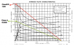
I already showed the 6k load line in post #13, so you can just tilt it up a liitle bit, for the actual instructions see Merlin's page here. Just a reminder, that the datasheets appear to be off a bit based on the samples that smoking-amp and myself have traced.well, i know i need some kind of step by step guide on how to plot a class AB load line with my 5k primary out tx, any takers..
Last edited:
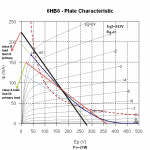
What's your B+ voltage? Class A looks ok but class B looks off - it should intersect B+ on the Ep axis or (Ep,0).Ok , here is me trying to do AB load line , i used jazbo8 curves
What's your B+ voltage? Class A looks ok but class B looks off - it should intersect B+ on the Ep axis or (Ep,0).
B+=375vdc same screen voltage 243vdc
Class B loadline 0.220ma at 1250=275vdc
cheers
skal
Last edited:
I see, in that case, the class A load line is wrong as well, so please look at Merlin's tutorials again, the class B load line must passes through B+ = 375V, and Imax = 375/1250 = 300mA. The class A load line needs to be shifted up by the idle current, so it passes through (375, Ia0), where Ia0 is the idle current.
- Status
- This old topic is closed. If you want to reopen this topic, contact a moderator using the "Report Post" button.
- Home
- Amplifiers
- Tubes / Valves
- 6HB6 as finals