I went through a bunch of the 6HB6s here on the curve tracer, trying to find a difference between the non windowed plate versions and the windowed plate versions. Not much difference. Both groups have a wide variance in plate curves and screen grid sensitivity. Only obvious difference was the non windowed versions tended to have some corrosion on the pins and maybe a small tilt toward more screen current.
Trying to get a matched pair of 6HB6s though, will be some excercise.
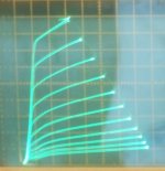
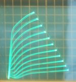
Here are a couple of widely different 6HB6 tube curves. (10 mA/div Vert., 50 V/div Horiz.) 1st tube curve is running with 105 V on g2 and the 2nd tube with 186 V on g2 (to get similar max current curves). Notice the difference in linearity (and gm) of the curve spacings for the same grid steps. Now they are not all this badly mis-matched, but you get the idea. You better have a bunch of these tubes to get something roughly matched. I've never seen tubes so all over the place as these.
Trying to get a matched pair of 6HB6s though, will be some excercise.
Here are a couple of widely different 6HB6 tube curves. (10 mA/div Vert., 50 V/div Horiz.) 1st tube curve is running with 105 V on g2 and the 2nd tube with 186 V on g2 (to get similar max current curves). Notice the difference in linearity (and gm) of the curve spacings for the same grid steps. Now they are not all this badly mis-matched, but you get the idea. You better have a bunch of these tubes to get something roughly matched. I've never seen tubes so all over the place as these.
Attachments
Last edited:
Man, those are some variances! From my small stash, I doubt I can even find a match pair, oh well, just have to trim them in the circuit. But great to know that these little guys can take some abuse!Here are a couple of widely different 6HB6 tube curves. (10 mA/div Vert., 50 V/div Horiz.) 1st tube curve is running with 121 V on g2 and the 2nd tube with 186 V on g2 (to get similar max current curves). Notice the difference in linearity (and gm) of the curve spacings for the same grid steps. Now they are not all this badly mis-matched, but you get the idea. You better have a bunch of these tubes to get something roughly matched. I've never seen tubes so all over the place as these.
I'm wondering if some tubes are gassy to get such big differences. I'm running the lower gm tube now to see if it improves with time (gettering action). So far the higher gm tube has just gotten higher. And the lower gm one has gotten worse! Diverging from each other more!
Doesn't look like either tube has been used before, but the low gm tube is acting like its got failing emission.
I tried cranking up the heater voltage on the low gm tube, and that improved it noticeably. But when I returned it to 6.3 V it was worse than before. A somehow failing tube I think. It must have insufficient emission to support the high current top range of the plate curves, so makes the gm look more constant. Both tubes drawing 9 mA of screen current, even with the widely divergent Vg2 required to get the same max plate current.
Time for a tube dissection. Where's that hammer.
Last edited:
"Time for a tube dissection. Where's that hammer."
If you take some photos, people here will be very happy!
I have a Ronald Dekker's μTracer and the only time I've come across similar situation was when I was measuring the triode section of PCL85: totally over the place in 17 pieces I have measured, but pentode section of same PCL85 group measures very tight. Strange, that little triode section is not "hi-tech" like 6HB6...
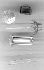
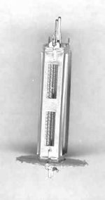
Here it is, whats left of it.
Those g1 wires look like they came from a frame grid, but its not on a frame. The grid is not flat, but curved around a bulged cathode. Must have been tricky to assemble. When I put the cathode into the g1, I can't see any obvious gap. So close! The scrapes on the cathode were from my pulling it out through the mica. Couldn't really see any thing wrong with the tube. A mystery.
I don't see how they could assemble this tube. There must be some trick to it, like the cathode sleeve being flat for insertion, then a long cam got inserted and twisted to bulge the cathode sleeve out. Or the cathode has some insulating coating over the emission coating to prevent shorts. Something going on here.
A person would go crazy, spending a lifetime, trying to assemble one of these tubes without some sneaky trick. Wonder if these were expensive originally.
Attachments
Last edited:
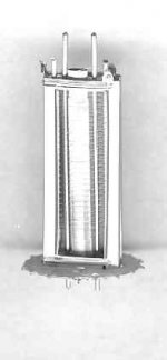
Hmmmm... interesting, g1 structure is different to g2 structure: no g1-g2 shadowing like in PL509 or 6EM5, for example. The g1 in 6HB6 obviously is made to have high gm instead low ig2. No problems, tubes like EL34 don't have g1-g2 shadowing.
In 6EM5 BPT the g1-g2 alignment is clearly visible even at external view, but gain and transconductance is only average.
In 6EM5 BPT the g1-g2 alignment is clearly visible even at external view, but gain and transconductance is only average.
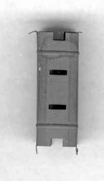
Yeah, no alignment for sure. About 5 to 1 grid pitch ratio. Although the g2 current spec is not too bad. Another mystery is the addition of the small slots in the sides of the plate, usually for inspection of grid alignment. There are long slots in the beam forming plate edges going the other way below the plate slots too. The beam forming plate has quite a large beam opening, maybe to emulate a pentode better.
Attachments
Last edited:
Here it is, whats left of it...
If it isn't broken, take it apart and mod it.
Now that is an appropriate signature to that picture


Some ideas to start checking:hi
having a bit of problem with the screen grid current , keeps moving up/down by about 4 to 5 volts , using red light distract screen reg out voltage 322vdc connect to screens , no af signal.
What could be causing this?
skal
If you have some resistor in series with screen grid you can measure the voltage drop in that resistor and calculate the current to know if output stage are oscillationg or drifting (excessive screen grid current significates trouble).
Regulators wander output when input is low than regulation headroom, so is good to check the reg input voltage.
Maybe it can be an regulator defect...
Humpty Dumpty was here.
Something about putting all those pieces back together.
I am since yesterday searching the Internet one case I read in 2008, where a seller OPENED some rare 8417 to clean inside (!!!
) but this can only be First April or a joke someone made, it is not possible ...Anyone heard of this case?
You are using this regulator? The Red Light District, p2hi DIYBras
i got 371vdc , and then a voltage drop 0f 44vdc across a resistor of 3k4 then 309vdc at the input of the reg and then output of reg is 304vdc is that enough head room.
cheers
skal
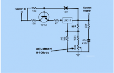
Maybe it need some 20V or more across "Raw +B in" to "Screen supply" to made them fully regulating, depending on the TIP50 characteristics.
If you are using something different you can make an schematic and post here to analyze the supply.
The 3k4 res are in series with the input, dropping 371V to 309Vdc at Red Light regulator input, is that right? 5V drop voltage is too little to that reg, at least when we raise the volume/signal....
If so you can try to reduce 3k4 dropper to maybe 470R or even less (only to protect the reg) and probably you can obtain the stable/correct voltage, if reg don't have some other problem. I can add a little heatsink to TIP50.
If so you can try to reduce 3k4 dropper to maybe 470R or even less (only to protect the reg) and probably you can obtain the stable/correct voltage, if reg don't have some other problem. I can add a little heatsink to TIP50.
Ok ,
this reg is pi**** me of now ,i have built a fresh board all new components , and it still now work as it should, now adjustment to the pot makes any different,s to the voltages.
could it i am reading the schematic wrong ? , i will draw up a fresh circuit diagram of my interpretation of how i see it .
- Status
- This old topic is closed. If you want to reopen this topic, contact a moderator using the "Report Post" button.
- Home
- Amplifiers
- Tubes / Valves
- 6HB6 as finals