I am in the design (Head Scratching) phase of building my first from scratch Hybrid Headphone Amp.
I will be using a single 6CG7 tube and a headphone buffer I have previously built and tested.
I have found some textbook 6SN7 designs and settled on what I think will work fine for a Class A gain stage to proceed my paralleled 4556 output buffer.
At this point I am looking for some guidance design wise from all of the seasoned veterans out there.
I see that this design will have 20db of gain (WAY too much), so I would like to implement 10-12db of NFB to reduce distortion and gain some bandwidth.
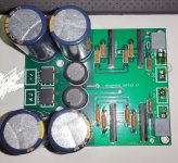
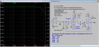
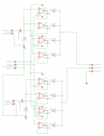
Attached are pictures of my design and my headphone buffer board.
Any Thoughts/Help is GREATLY appreciated.
I will be using a single 6CG7 tube and a headphone buffer I have previously built and tested.
I have found some textbook 6SN7 designs and settled on what I think will work fine for a Class A gain stage to proceed my paralleled 4556 output buffer.
At this point I am looking for some guidance design wise from all of the seasoned veterans out there.
I see that this design will have 20db of gain (WAY too much), so I would like to implement 10-12db of NFB to reduce distortion and gain some bandwidth.
Attached are pictures of my design and my headphone buffer board.
Any Thoughts/Help is GREATLY appreciated.
Attachments
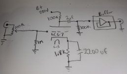
6CG7 is equivalent to 6SN7. As such, 100k load resistor looks very high for 6SN7 especially since you don't need much gain. I'd reduce it to 18K and bias to 8mA @ Vgk -4V.. which means 500R cathode resistor.. Gain is around 15x. If still too high, choose between koonw's way of GNFB or split the 18k load resistor between plate and cathode.. example 12k on the plate and 5k6 under the cathode bias resistor (a la concertina phase splitter).
edit: missing essential info: what is the input impedance of your solid state buffer?
edit: missing essential info: what is the input impedance of your solid state buffer?
YOU GUYS ARE GREAT!
This is awesome.
I agree higher current is preferred.
I currently have about 7.5mA on my 6CG7 Aikido and I am VERY happy with the result.
I believe I am using Rp 8k5Ω and Rk 470Ω, I think I will stick with this 7.5mA operating point.
Koonw, could you run those please?
I would like to have have a final gain level of around 6-8db after NFB, I would like to keep gain prior to NFB under 12db though, there is no need to create noise with the gain just to burn it off in the NFB.
So sticking with the B+280, Plate @ 7.5mA, Gross Gain 12db, Net Gain 6-8db after NFB.......What would this need to be Koonw?
Thank You guys SO MUCH!
Rich
YOU GUYS ARE GREAT!
This is awesome.
I agree higher current is preferred.
I currently have about 7.5mA on my 6CG7 Aikido and I am VERY happy with the result.
I believe I am using Rp 8k5Ω and Rk 470Ω, I think I will stick with this 7.5mA operating point.
Koonw, could you run those please?
I would like to have have a final gain level of around 6-8db after NFB, I would like to keep gain prior to NFB under 12db though, there is no need to create noise with the gain just to burn it off in the NFB.
So sticking with the B+280, Plate @ 7.5mA, Gross Gain 12db, Net Gain 6-8db after NFB.......What would this need to be Koonw?
Thank You guys SO MUCH!
Rich
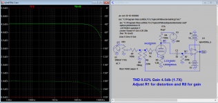
No problem.
With Rp 8.5k, Rk 470, the sim Ik is just over 9.9mA, distortion 0.05% to 0.1%
Gross gain 15.7db (6X), distortion 0.5%
R8 Net Gain db
560K 8.65
470k 7.8
390k 6.8
270k 4.6
With Rp 18K Ik is 7.2mA gross gain ~20 db (9X), distortion 0.64%
Attachments
Last edited:
I'm on my second all tube headphone amp, and I love it. My personal preference would be to operate the triode input stage without any NFB. I suggest replacing the 100K resistor at the input of the buffer with a resistor voltage divider. 68k and 33k will provide about 10dB attenuation, assuming the input impedance of the buffer is much higher than 33k. The tube stage has more than enough plate voltage swing to do this, and the buffer stage already has plenty of NFB. You may need to adjust the values of the voltage divider if the input impedance of the buffer is lower than about 100k. I also see some good advice above on optimizing the tube stage. Experiment a bit and I think you will enjoy the sound.
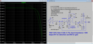
Is it possible to target 15db gross gain with a bias level around 8-9mA?
Yes, with Rp 10K, Rk 680, Ik 8mA, open loop gain is 15db(5.5X),distortion 0.4%, . With R8 as follows, net distortion 0.05%-0.1%
R8 Net Gain db
560K 8.2
470k 7.5
390k 6.5
270k 4.3
Yes, with Rp 10K, Rk 680, Ik 8mA, open loop gain is 15db(5.5X),distortion 0.4%, . With R8 as follows, net distortion 0.05%-0.1%
R8 Net Gain db
560K 8.2
470k 7.5
390k 6.5
270k 4.3
Distortion in triodes is directly proportional to output level. If you do not specify output level then distortion figures are meaningless.
Cheers
Ian
Well, I'm figuring on my input device being an iPod or something.
So input level about 500mV, let's say my input level design be 775mV.
That being said, I want to have a max output from the tube be 7V.
Maybe this will help the progress.
That should put my gross gain at 20db.
Maybe I can have a hi/lo gain switch or something?
So input level about 500mV, let's say my input level design be 775mV.
That being said, I want to have a max output from the tube be 7V.
Maybe this will help the progress.
That should put my gross gain at 20db.
Maybe I can have a hi/lo gain switch or something?
Last edited:
- Status
- This old topic is closed. If you want to reopen this topic, contact a moderator using the "Report Post" button.
- Home
- Amplifiers
- Tubes / Valves
- 6CG7 Hybrid Tube Headphone Amp