Distortion in triodes is directly proportional to output level. If you do not specify output level then distortion figures are meaningless.
Cheers
Ian
The input is 1V (as sch attached previously), you got the output level (same as net gain level). I know one will like to see distortion reference to 1V RMS output level. Thank you.
Zeroing In On The Final Design
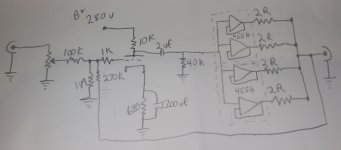
Here is what I think I will be building.
Koonw, Can you please Spice this up for me?
You have been SO helpful, Thank You.
The 40K resistor could be swapped for something higher if need be.....
The dual parallel 4556 opamps in a buffer arraingement will allow plenty of current for low impedance hogs.
The 6-15db of gain will allow for driving high voltage needs into 600+Ω cans.
Attachments
Here is what I think I will be building.
Koonw, Can you please Spice this up for me?
You have been SO helpful, Thank You.
The 40K resistor could be swapped for something higher if need be.....
The dual parallel 4556 opamps in a buffer arraingement will allow plenty of current for low impedance hogs.
The 6-15db of gain will allow for driving high voltage needs into 600+Ω cans.
No much problem.
Attachments
OK, this looks very interesting.
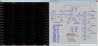
It would be easy to change R7 out for 100k would this change the loading on the 6CG7?
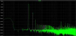
Why is there a bit of bottom end lift and top end droop once NFB is applied heavily?
Or is that bottom trace a phase plot of some kind?
I change R7 from 100k to 50k, the level increased a bit but distortion increased from 0.5% to 0.8%, no other is affected.
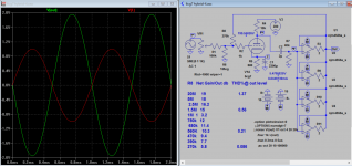
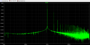
Don't worry about the bottom end lift, just that I don't set sufficient time to display correctly, now I have re-plotted using longer timing. The top end lift is for real due to level NFB applied. I won't worry since the level is so low.
Attachments
Last edited:
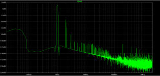
That looks pretty nice!
Anything below 2nd harmonic looks like it's totally in the dirt.
I'm excited to build this HPA.
I have already received a few transformer quotes.
I've speccd the tranny for, 210V 50mA, 12.6V 1A, 9V 1.2A, 9V 1.2A.
The 2 9V secondaries will power the bipolar supply on the buffer circuit.
I will rectify and regulate the 12.6V with an LM317 for the heater on the 6CG7.
The 210 should put me right around 290V raw B+ with FWB rectification.
- Status
- This old topic is closed. If you want to reopen this topic, contact a moderator using the "Report Post" button.
- Home
- Amplifiers
- Tubes / Valves
- 6CG7 Hybrid Tube Headphone Amp