How is it possible that it works?
Hi to all... sorry for the intrusion. I've seen there is a lengthy discussion going on about the 6C33C-B (actually, 6S33S-V, but never mind... we are all used to calling russian tubes by their western "names")... and I would not want to intrude on that, since I did not read anything.
Still, if I am not out of line here, I would like to know two things -- has anyone participating in this thread tought of adopting higher Ra for the output tube, like i.e. 3k or at least 2.5k, instead of the punishingly low i.e. 600 ohm or 1k? Yes, you would loos a lot of power, but gain quite a lot in the distortions and "damping" department... what you loose in power you could gain by lowering the current and passing to higher B+... anyone got any comments on that (sorry if it has already been asked or said)!
Furthermore, I noticed that there is a Mr. Ari Polisois -- is it the famous author of the different 6C33C amp mentioned in Valve magazine... and of the unusual biasing method for output tubes?
If it is, I would like him to answer a simple question -- how is that possible, that you can actually place one power supply on top of another, and not have current from the upper connected thru the lower ps to ground... what I want to say, the upper is much stronger than the lower one... and I doubt that current is "willing" to turn in circles just in the upper circuit, without any interaction with the lower circuit?
Regards to all, and sorry for the intrusion!
Aleksandar
Re: How is it possible that it works?
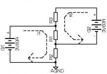
Well, from an "audio designer" one would expect at least elementary knowledge of electrotechnics. The picture below is self-explanatory.
Alex Kitic said:.....If it is, I would like him to answer a simple question -- how is that possible, that you can actually place one power supply on top of another, and not have current from the upper connected thru the lower ps to ground... what I want to say, the upper is much stronger than the lower one... and I doubt that current is "willing" to turn in circles just in the upper circuit, without any interaction with the lower circuit?.....
Well, from an "audio designer" one would expect at least elementary knowledge of electrotechnics. The picture below is self-explanatory.
Attachments
Yes Alex,
This is how it works ( as Moamp explained).
Two separate current loops.
Thanks anyway for your interest and nice words.
Regarding the load, I agree with you.
I used also 1 k load ( did not go further because, as you know,
the 6C33C-B has an internal resistance of about 100 ohms ) and
I confirm that the distortion drops significantly.
However, I am know experimenting three parallel 6C33 ( resulting internal resistance circa 30 ohms ) and a 75 ohm load,
the same as a TV cable . I still can't tell if it has some kind of
interest.
Cheers,
Ari.
By the same message : thank you Moamp.
Dear Kuei Yang,
I read carefully your reply and I think I'll read it again.
In the meantime, going to a real and practical ground, what
impedance would you give the plate choke, what capacitance to
the coupling capacitor and what parameters would the output transformer have.
If you have some personal experience on the matter, kindly let me know.
Ari.
Kuei Yang,
Sorry, I forgot to mention, for a 6C33 valve and expected output
power of, say, 15 Watts, and a frequency range ( within -3dB ), of 35 Hz to 30 kHz, which is roughly the performance of the Simplex.
Also, if you know it, what would the plate choke cost and its dimensions and weight.
Thanks again.
AriPS - Diyourselfers are usually happy to learn theories, but need practical solutions.
Konnichiwa,
You can get parallel feed paraphenelia from Magnequest/Bottlehead.com (nothing for 6S33 though).
I have experimented with parallel feed and prefer optimised series feed solution by and large. I merely took exception to you making fundamentally false statements about how the circuits (both of them) work.
As to "Anode Load Choke", lets assume we have a standard 600R/220mA Transformer and remove the secondary.
This frees up between 30 - 50% of the winding space and as we don't need to worry as much about losses we can easily put 2-3 times the turns onto the same core and likely get at least 3 - 4 times the inductance commonly found in a series feed transformer, which for our 6S33 anode load choke could easily make 10+++H, which is enough to keep the choke in effect out of contention when it comes to wrangeling for signal current.
For our parallel feed transformer we can use a 2" stack of pattern 38 48% Nickel Permalloy, this should handle around 12 - 15 Watt. As no gap is needed and we use high permability core material we will have tons of primary inductance, so that the capacitor value for the coupling cap is determined primarily by the reflected load, say 600R. To couple to 600R with a -3db point of 10Hz takes 25uF (we can use metal encased motor run MKP).
However, as typhical (reflex) speakers often tend to have a rising impedance below cutoff we usually couple to a much higher impedance than nominal, so in practice lower values tend to work out fine. Equally, if we couple to a sealed box speaker we will have an impedance rise around the resonance which also tends to be around the cutoff of the speaker, so we are actually coupling into a much higher than nominal impedance again, so we need not worry again with undersized coupling capaictors.
At any extent, we are much smaller in value thanm the usual PSU Capacitor.
BTW, if you use series feed AND self bias you8 can eaily work around the problem of having the PSU Cap also as coupling cap, look up "ultrapath".
Anyway, enough of that, it is all ancient history and should be really plainly obvious to anyone.
Sayonara
ari polisois said:Also, if you know it, what would the plate choke cost and its dimensions and weight.
You can get parallel feed paraphenelia from Magnequest/Bottlehead.com (nothing for 6S33 though).
I have experimented with parallel feed and prefer optimised series feed solution by and large. I merely took exception to you making fundamentally false statements about how the circuits (both of them) work.
As to "Anode Load Choke", lets assume we have a standard 600R/220mA Transformer and remove the secondary.
This frees up between 30 - 50% of the winding space and as we don't need to worry as much about losses we can easily put 2-3 times the turns onto the same core and likely get at least 3 - 4 times the inductance commonly found in a series feed transformer, which for our 6S33 anode load choke could easily make 10+++H, which is enough to keep the choke in effect out of contention when it comes to wrangeling for signal current.
For our parallel feed transformer we can use a 2" stack of pattern 38 48% Nickel Permalloy, this should handle around 12 - 15 Watt. As no gap is needed and we use high permability core material we will have tons of primary inductance, so that the capacitor value for the coupling cap is determined primarily by the reflected load, say 600R. To couple to 600R with a -3db point of 10Hz takes 25uF (we can use metal encased motor run MKP).
However, as typhical (reflex) speakers often tend to have a rising impedance below cutoff we usually couple to a much higher impedance than nominal, so in practice lower values tend to work out fine. Equally, if we couple to a sealed box speaker we will have an impedance rise around the resonance which also tends to be around the cutoff of the speaker, so we are actually coupling into a much higher than nominal impedance again, so we need not worry again with undersized coupling capaictors.
At any extent, we are much smaller in value thanm the usual PSU Capacitor.
BTW, if you use series feed AND self bias you8 can eaily work around the problem of having the PSU Cap also as coupling cap, look up "ultrapath".
Anyway, enough of that, it is all ancient history and should be really plainly obvious to anyone.
Sayonara
stupid me!
Well, if it were not for that harsh answer, I would have never gathered the will to simulate the circuit -- and of course, stupid me. It only proves I'm human, too.
Yes, it does work, and it works great! So many times I wanted to try it, but I just could not envisage it appropriately. We sometimes remain blind to the obvious...
On the other hand, I would have preferred a reply from Mr. Polisois...
Generally speaking, my father taught me to dislike people wearing dark glasses. Why? Because it cover their eyes, they hide themselves behind those glasses. That might not be an obvious truth, but audio designers and "audio designers" (whatever do the marks mean) usually sign with their name. Others don't.
Thanks for the eye opener, Mr. Moamps... I'm happy to hear that you have heard of me! It's a pity I have never heard of you, and most probably never will, since you probably do sign your work with your own name.
Regards to all... if someone would like to reply to the issue about Ra, I would be more than happy to discuss.
Aleksandar
Re: stupid me!
Just wondering who it was who said "tired of... reading lots of mumbo-jumbo by people who did not give too much of a tought to what they are saying/writing".
BTW, sorry dude...never heard of you until a couple of days ago when I first came across your memorable pearls of wisdom. I also liked this one with your dad and the glasses Keep up the good work
For those of you who don't know me, my name is Amps, Mo'Amps.
Alex Kitic said:...Thanks for the eye opener, Mr. Moamps...
Just wondering who it was who said "tired of... reading lots of mumbo-jumbo by people who did not give too much of a tought to what they are saying/writing".
BTW, sorry dude...never heard of you until a couple of days ago when I first came across your memorable pearls of wisdom. I also liked this one with your dad and the glasses
Keep up the good work For those of you who don't know me, my name is Amps, Mo'Amps.
Kuei Yang Wang said:Before I forget, I hope you realise that your grid circuit signal also couples through a coupling capacitor in DCMB, again a powersupply electrolytic.
This demonstrates that there is no free lunch (except if you the "free lunch" circuit of course) and if you remove one capacitor so link two points having different DC potential for AC you need to replace it with another one.
Hi Thorsten,
The DCMB circuit avails itself of a feature that actually does provide some degree of free lunch. Because output tube grid and cathode are both coupled to the driver PS, driver PS noise is partially---and cleanly---cancelled. I say "cleanly" because any noise appearing on the driver PS appears in-phase on both output grid and cathode. The grid-cathode circuit element is about as truly differential as one can find in any active circuit.
In Ari's circuit, static measurements suggest the overall driver PS noise cancellation is about 75%. That figure, if accurate (the measurement is somewhat tentative, requiring further confirmation), effectively removes from the circuit 75%, if you will, of any capacitor used in the driver PS and any line noise.
Ari's circuit possibly can be tweaked to render the 75% figure higher, and in any event the circuit probably could otherwise be changed to implement DCMB coupling between input and driver, allowing the further benefit of noise cancellation on the input circuit.
What is not cancelled in DCMB is noise on the output circuit. That noise, however, is of less concern, relatively speaking, because the ratio of comparative voltages---B+ noise voltage to signal voltage---is higher. Experimentation might show that using parafeed on the output, and DCMB coupling for all stages but the output, is the better of combinations? Mind you, a DCMB circuit could be constructed using only high quality capacitors, rendering parafeed of doubtful extra value (except, perhaps, cost).
Cheers.
Konnichiwa,
I would have to check the 75% figure, but I probably still prefer 100% of a Silver Leaf & Teflon or Mica capacitor (sound) in a classic series coupling circuit to 25% of a cheap electrolytic.
As you might have noticed, I have done a lot work on DC coupled circuits and I am aware of both pitfalls and benefits.
My view on DCMB is that a modest increase in efficiency (due to the seperate driver supply) is traded for added potential problems, compared to classic direct coupled circuits (Loftin White etc.). As it is it seems to represent a rather ingenious solution looking for a problem that does not really exist.
But I was not really criticing Ari's circuit (though it has plenty to be criticised), I took exception merely to his assertations that direct coupling removed the coupling capacitor (it does not do so if two supplies are used, it merely shifts the coupling capacitors position) and that parallel feed output circuits introduce a coupling capacitor not present in series feed circuits.
And a correctly implemented "Monkey/DRD" circuit can be implemented to elimiate the issue, so what?
Well, assuming we merely want to provide a circuit that offers maximal transparency and elimination of as many stages as well as of as many capacitors exposed to audio signals plus the ability to drive a given output valve to full available power it should be obvious that a variation of Gary Pimm's Direct Coupled Active Load 300B Circuit is a MUCH BETTER bet.
If we replace the cathode ballast resistor with a valve instead so that we have 1 X KT88 for the 300B Anode load and 1 X KT88 for the cathode load plus 1 X WE437 or suitable similar types as driver and (say) a 5687 or EL84 as anode load for that we could have a circuit that offers maximum insulation from the PSU, regardless what it actually is and only 1 Resistor plus one capacitor and two triodes as well as the parallel feed output transformer (shall we make it with high nickel content amorphous core, silver foil secondary and silver wire primary while ae are at it?) in the signal circuit.
Okay, with a 1200V/100mA supply and an extra 40 Watt or so heater power to get 6-8 Watt per channel it starts rivaling Nelson Pass's "Son of Zen" Amplifier for inefficiency, but we are after all after quality, not efficiency?
Anyway, back to making RC coupled amplifiers using series feed output transformers. There are many reasons why they still represent overall a better balance of pro's and con's.
Sayonara
serengetiplains said:The DCMB circuit avails itself of a feature that actually does provide some degree of free lunch. Because output tube grid and cathode are both coupled to the driver PS, driver PS noise is partially---and cleanly---cancelled. I say "cleanly" because any noise appearing on the driver PS appears in-phase on both output grid and cathode. The grid-cathode circuit element is about as truly differential as one can find in any active circuit.
In Ari's circuit, static measurements suggest the overall driver PS noise cancellation is about 75%. That figure, if accurate (the measurement is somewhat tentative, requiring further confirmation), effectively removes from the circuit 75%, if you will, of any capacitor used in the driver PS and any line noise.
I would have to check the 75% figure, but I probably still prefer 100% of a Silver Leaf & Teflon or Mica capacitor (sound) in a classic series coupling circuit to 25% of a cheap electrolytic.
As you might have noticed, I have done a lot work on DC coupled circuits and I am aware of both pitfalls and benefits.
My view on DCMB is that a modest increase in efficiency (due to the seperate driver supply) is traded for added potential problems, compared to classic direct coupled circuits (Loftin White etc.). As it is it seems to represent a rather ingenious solution looking for a problem that does not really exist.
But I was not really criticing Ari's circuit (though it has plenty to be criticised), I took exception merely to his assertations that direct coupling removed the coupling capacitor (it does not do so if two supplies are used, it merely shifts the coupling capacitors position) and that parallel feed output circuits introduce a coupling capacitor not present in series feed circuits.
serengetiplains said:Ari's circuit possibly can be tweaked to render the 75% figure higher,
And a correctly implemented "Monkey/DRD" circuit can be implemented to elimiate the issue, so what?
serengetiplains said:Experimentation might show that using parafeed on the output, and DCMB coupling for all stages but the output, is the better of combinations? Mind you, a DCMB circuit could be constructed using only high quality capacitors, rendering parafeed of doubtful extra value (except, perhaps, cost).
Well, assuming we merely want to provide a circuit that offers maximal transparency and elimination of as many stages as well as of as many capacitors exposed to audio signals plus the ability to drive a given output valve to full available power it should be obvious that a variation of Gary Pimm's Direct Coupled Active Load 300B Circuit is a MUCH BETTER bet.
If we replace the cathode ballast resistor with a valve instead so that we have 1 X KT88 for the 300B Anode load and 1 X KT88 for the cathode load plus 1 X WE437 or suitable similar types as driver and (say) a 5687 or EL84 as anode load for that we could have a circuit that offers maximum insulation from the PSU, regardless what it actually is and only 1 Resistor plus one capacitor and two triodes as well as the parallel feed output transformer (shall we make it with high nickel content amorphous core, silver foil secondary and silver wire primary while ae are at it?) in the signal circuit.
Okay, with a 1200V/100mA supply and an extra 40 Watt or so heater power to get 6-8 Watt per channel it starts rivaling Nelson Pass's "Son of Zen" Amplifier for inefficiency, but we are after all after quality, not efficiency?
Anyway, back to making RC coupled amplifiers using series feed output transformers. There are many reasons why they still represent overall a better balance of pro's and con's.
Sayonara
Hi,
Or rather shouldn't exist IMO.
The problem with those hat & bunny tricks such as direct coupling is that they're just an illusion deluding the public, worse even it deludes it's own designer into thinking they have a problem solved where in reality they introduced a few others in a rather trojan horselike way....
It does not do so if one PS or more is used either.
Looking at the AC loops will tell you that straight away.
What you CAN do is reduce the effect of those caps on the audio part of the circuit proper to the bare minimun.
Not so as far as the OPT is concerned, there's more to a parallel feed circuit than meets the eye.
Meaning that you have to look beyond the mere presence of yet another of those oh so horrible caps in the signal path, see what you gain by ommiting it, see what you gain by including it, then make up your mind about what you want to be living with.
Cheers,
As it is it seems to represent a rather ingenious solution looking for a problem that does not really exist.
Or rather shouldn't exist IMO.
The problem with those hat & bunny tricks such as direct coupling is that they're just an illusion deluding the public, worse even it deludes it's own designer into thinking they have a problem solved where in reality they introduced a few others in a rather trojan horselike way....
(it does not do so if two supplies are used, it merely shifts the coupling capacitors position)
It does not do so if one PS or more is used either.
Looking at the AC loops will tell you that straight away.
What you CAN do is reduce the effect of those caps on the audio part of the circuit proper to the bare minimun.
Mind you, a DCMB circuit could be constructed using only high quality capacitors, rendering parafeed of doubtful extra value (except, perhaps, cost).
Not so as far as the OPT is concerned, there's more to a parallel feed circuit than meets the eye.
Meaning that you have to look beyond the mere presence of yet another of those oh so horrible caps in the signal path, see what you gain by ommiting it, see what you gain by including it, then make up your mind about what you want to be living with.
Cheers,
fdegrove said:Not so as far as the OPT is concerned, there's more to a parallel feed circuit than meets the eye.
Meaning that you have to look beyond the mere presence of yet another of those oh so horrible caps in the signal path, see what you gain by ommiting it, see what you gain by including it, then make up your mind about what you want to be living with.
Hi Frank, nice meeting you here. Wow, it's hard discussing with Thorsten, I mean, I post and have to cool off for a day or so to allow myself to recommit to the sparing use of adverbs. Mind you, I'd be the first to admit I get more bang for the buck in my Zen studies after a rousing session DIY fun.
You're right to suggest I oversimplified the grab-bag called parafeed. And I do agree that the presence of an OPT constitutes a net negative, sonically speaking, which is why I can often be found in my garage working under my heat-free lights, fleshing out my design for the perfect OPT. I've discovered it can be constructed, but using only the energy of cold fusion, and even then needs to be operated at absolute zero temperature, and topped by a Shakti stone, for best sonic effect. Brrrrrrrr!
Hi,
LOL....
Yeah, know what you mean but you really should get past that or you'll be renewing your Zen studies in a hurry....
Either way, the points raised are valid and as I said it's all a matter of picking the poison that suits you best in the context of synergy with the other components, mostly the loudseakers/room, of your system.
I don't want to wax philosophical but you know what I try to avoid in my system as it's just not worth spending too much time in the garage on IMO....
That, however, is my poison and therefore a choice of what constitutes to my ears the best set of compromises.....
Cheers,
Wow, it's hard discussing with Thorsten, I mean, I post and have to cool off for a day or so to allow myself to recommit to the sparing use of adverbs.
LOL....
Yeah, know what you mean but you really should get past that or you'll be renewing your Zen studies in a hurry....
Either way, the points raised are valid and as I said it's all a matter of picking the poison that suits you best in the context of synergy with the other components, mostly the loudseakers/room, of your system.
I don't want to wax philosophical but you know what I try to avoid in my system as it's just not worth spending too much time in the garage on IMO....
That, however, is my poison and therefore a choice of what constitutes to my ears the best set of compromises.....
Cheers,
THE TRASHER!
Moamps...
Is a legitimate question mumbo-jumbo?! If it is, then most of the people here should feel the same disdain!
I don't believe it... you must be some figure from "Man in Black"?
Please, Moamps, keep your wise comments to yourself -- if you've got no "pearls of wisdom" to share. It is obvious that we used to live in the same country once -- mine is still full people like you.
Let us not pollute this forum with unnecessary replies (lecenjem tvojih kompleksa, bato).
Moamps...
Just wondering who it was who said "tired of... reading lots of mumbo-jumbo by people who did not give too much of a tought to what they are saying/writing".
Is a legitimate question mumbo-jumbo?! If it is, then most of the people here should feel the same disdain!
For those of you who don't know me, my name is Amps, Mo'Amps.
I don't believe it... you must be some figure from "Man in Black"?
Please, Moamps, keep your wise comments to yourself -- if you've got no "pearls of wisdom" to share. It is obvious that we used to live in the same country once -- mine is still full people like you.
Let us not pollute this forum with unnecessary replies (lecenjem tvojih kompleksa, bato).
Aleks, I shared my wisdom with you and you felt offended by it, resenting such stupid things as it having been me who, in your words, "opened your eyes" not Ari (who himself thanked me for posting; btw, you didn't address your question to him but to "all") or using a nick on the forum like most of us here. It's obvious who started this "unneccesary replies" thing. What really amazes me is how a couple of jokes gave your self-righteous irrationality a real boost so now you're drawing in whole countries and people living in them, accusing me of chovinism or what? That's rich. Get real, stop throwing low punches if you don't have the stomach to fight and watch your own mouth before you start giving lessons to other people. And don't worry, no more wisdom for you, promise.
Dear Kuei Yang,
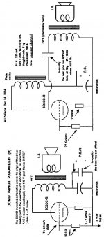
You will find, in the attached file, an attempt of comparing Parafeed and DCMB.
I must admit that I am not very familiar with the Parafeed subtilities, therefore, if you find something missing in my sketch,
kindly let me know.
On the other hand, I listed on the text file that I am sending after this message, the stron points of the DCMB topology, that I happen to know, having used this circuitry for 5-6 years now, in many amplifiers that I have designed and built, mainly to support some articles that have been published by Glass Audio, AudioXpress and the Italian diy magazine Costruire HI FI, but also ( half a dozen ) for my friends and myself.
I will appreciate your comments, hopefully calm, cool and collected.
Cheers,
Ari.
Attachments
Konnichiwa,
Hmmm. That is like comparing an Ak-47 to a Lee Enfield.
Given that Parallel Feed is relevant to the output current loop (anode to cathode) and DCMB is relevant to the input current loop (grid to cathode). So I am not sure what you attempt to compare.
You can compare series feed to parallel feed, I believe I have done that already.
I think the problems you have are not in the subtleties.
BTW, please make sure you are aware how REAL capacitors behave. That might make clear why "bypassing" actually does not mean that automatically the smaller value "high quality" capacitor is the one carrying the signal current. Again, most basic EE101.
(I say this because your drawing inaccuratly seems to imply that in either case the capacitor in series with load is the same "high quality" one and the Electrolytic is not relevant, you may find the revers true if you actually apply sufficient analysis to the concept)
I am not aware of any "strong" points, at least non whatsoever that are sepcific or unique to DCMB (please appreciate that I have been aware of it since your first publication and took the pains to analyse it exhaustively - I am quite aware how it works) and in many cases other circuits (like the basic RC coupled one) can be illustrated to be ultimatly less plagued by the issues you have choosen to use as points in favour of DCMB.
Non of this BTW has got any bearing on personal preferences or any such issues, including "good sound", The issue is merely that your statement which claims DCMB eliminates coupling capaictors is absolutely inaccurate, as it merely shifts the position of said coupling capacitor. Thus, if your aim in devising DCMB was to "eliminate" from the signal path "poor quality capacitors", you have suceeded in achieving the exact opposite of your aim.
There are of course many isses past the signal passing through a capacitor that are relevant and may argue in favour of DCMB, but you have coosen to not remark on these.
It may have escaped you so far, my comments are always calm and collected. I observe, I remark on my observations and I recommedn remedies where I percieve problems. And rest assured, I do so with great calm and collectedness.
Sayonara
ari polisois said:You will find, in the attached file, an attempt of comparing Parafeed and DCMB.
Hmmm. That is like comparing an Ak-47 to a Lee Enfield.
Given that Parallel Feed is relevant to the output current loop (anode to cathode) and DCMB is relevant to the input current loop (grid to cathode). So I am not sure what you attempt to compare.
You can compare series feed to parallel feed, I believe I have done that already.
ari polisois said:I must admit that I am not very familiar with the Parafeed subtilities,
I think the problems you have are not in the subtleties.
BTW, please make sure you are aware how REAL capacitors behave. That might make clear why "bypassing" actually does not mean that automatically the smaller value "high quality" capacitor is the one carrying the signal current. Again, most basic EE101.
(I say this because your drawing inaccuratly seems to imply that in either case the capacitor in series with load is the same "high quality" one and the Electrolytic is not relevant, you may find the revers true if you actually apply sufficient analysis to the concept)
ari polisois said:On the other hand, I listed on the text file that I am sending after this message, the stron points of the DCMB topology, that I happen to know, having used this circuitry for 5-6 years now, in many amplifiers that I have designed and built, mainly to support some articles that have been published by Glass Audio, AudioXpress and the Italian diy magazine Costruire HI FI, but also ( half a dozen ) for my friends and myself.
I am not aware of any "strong" points, at least non whatsoever that are sepcific or unique to DCMB (please appreciate that I have been aware of it since your first publication and took the pains to analyse it exhaustively - I am quite aware how it works) and in many cases other circuits (like the basic RC coupled one) can be illustrated to be ultimatly less plagued by the issues you have choosen to use as points in favour of DCMB.
Non of this BTW has got any bearing on personal preferences or any such issues, including "good sound", The issue is merely that your statement which claims DCMB eliminates coupling capaictors is absolutely inaccurate, as it merely shifts the position of said coupling capacitor. Thus, if your aim in devising DCMB was to "eliminate" from the signal path "poor quality capacitors", you have suceeded in achieving the exact opposite of your aim.
There are of course many isses past the signal passing through a capacitor that are relevant and may argue in favour of DCMB, but you have coosen to not remark on these.
ari polisois said:I will appreciate your comments, hopefully calm, cool and collected.
It may have escaped you so far, my comments are always calm and collected. I observe, I remark on my observations and I recommedn remedies where I percieve problems. And rest assured, I do so with great calm and collectedness.
Sayonara
- Status
- This old topic is closed. If you want to reopen this topic, contact a moderator using the "Report Post" button.
- Home
- Amplifiers
- Tubes / Valves
- 6c33 Se