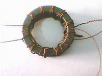
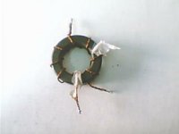
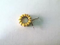
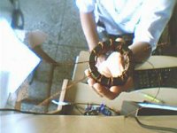
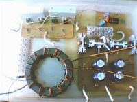
notice that the different modules r not good looking.my main concern was to have a robust,tough and durable ckt.i have used 10 strands of wire for sec. and 25 strands for primary windings.
the wire used is .5mm dia copper wires,3 of them each in a single wire.
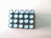
mosfets r 20amp each.diodes 10amp max each.will upgrade diodes when needed to atleast 35amp each.
core is monestrous 14cm dia ,costed a hell.i teasted it in college and it was continously supplying 900w without any strain on core(remained warm)!!!!using more powerful diodes,fans and more mosfets,it can safely go to 1600w(i believe).
i need 300w only lest my car battery will dry up in a sec.but what i wanna convey is that the smps is capable,supplies 30v.so i have a capable power supply for the car amps.whatever watts the amp desires smps has the capability
reviews please")
the wire used is .5mm dia copper wires,3 of them each in a single wire.
mosfets r 20amp each.diodes 10amp max each.will upgrade diodes when needed to atleast 35amp each.
core is monestrous 14cm dia ,costed a hell.i teasted it in college and it was continously supplying 900w without any strain on core(remained warm)!!!!using more powerful diodes,fans and more mosfets,it can safely go to 1600w(i believe).
i need 300w only lest my car battery will dry up in a sec.but what i wanna convey is that the smps is capable,supplies 30v.so i have a capable power supply for the car amps.whatever watts the amp desires smps has the capability
reviews please
sagarverma said:hi xplode,
good link.great one i should say.i always had probs with xformer winding.ckt was finished in few hours(from pcb to full done),but perfect xformer wiring was a pain in ***.wind unwind wind unwind........to get symmetrical o/p.
hi homer,
couldnt post bec of festive season.will post the pics soon(today).how much u done smps?made tripath amp????
hey sagarverma, hope you enjoyed your holidays.
nice work! love to see you crank out function over form smps's. keep em coming
i hope i have an easier time winding...
im still waiting for a free sample from an inductor manufacturer to use as a core. i basically havent started anything yet

i want to upgrade my head unit first.
as for building tripath amp, im leaning to biting the bullet and coughing up the cash for 3 kits.
hi homer,
a car is a harsh environment,so the smps i have made had to b as much robust as i can make.the solder connections are like mini mountains.very thick tracks bec at the end of it all,i dont want anyone sitting in the car to say that the system u made really looks as if u made it.i want professional quality,no matter how ugly it looks.bec at the end of it,its only the music that u hear and not see the circuitary behind the magic.
i hope u will help me through the class d when u realise them
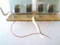
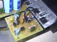
Looks like your are amking good progress.
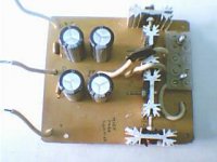
Here a pic of my current project, the supply module is of the schematic I tried in vein to post before.
I am not sure of it maximum output, supply rails are 35+/- and it can swing those to power module in while in bridge mode to 30v +/- into 4 ohm or 60 volts into 4 ohms.
Here a pic of my current project, the supply module is of the schematic I tried in vein to post before.
I am not sure of it maximum output, supply rails are 35+/- and it can swing those to power module in while in bridge mode to 30v +/- into 4 ohm or 60 volts into 4 ohms.
Attachments
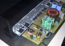
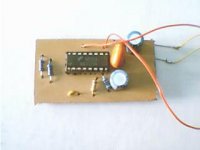
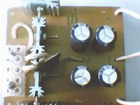
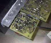
And the board layout.
I unfortunately lost the schem to the amplifier module but will recreate it if anyone is interested.
They are super simple, stable, and powerful using onsemi mjh6284/6287 comp pairs.
They sound ok but this not a prob I intend to use this for low frequencies.
I unfortunately lost the schem to the amplifier module but will recreate it if anyone is interested.
They are super simple, stable, and powerful using onsemi mjh6284/6287 comp pairs.
They sound ok but this not a prob I intend to use this for low frequencies.
Attachments
- Status
- This old topic is closed. If you want to reopen this topic, contact a moderator using the "Report Post" button.
- Home
- Amplifiers
- Class D
- 6 channel class-d amp for car, need guidance...