Thanks SY, I'll try first the schematic I've post then I'll go for something better...sometimes it is better to walk on a longer way instead the shorter. I'll learn more...maybe... ") I'm making the test board in this moment...we'll see tomorrow.
I'm making the test board in this moment...we'll see tomorrow.
Second steps will be to change first mje350 with a 2n2907 that have an Hfe greater. What about the design I've post? Can works? I heve to change something in your opinion?
And now...what are you doing in Alba? Are you often in Italy?
Ciao Mark
I'm making the test board in this moment...we'll see tomorrow. Second steps will be to change first mje350 with a 2n2907 that have an Hfe greater. What about the design I've post? Can works? I heve to change something in your opinion?
And now...what are you doing in Alba? Are you often in Italy?
Ciao Mark
Re: R loading - I don't bother with resistive loads any more. I use inductance whenever possible, and CCS when I dont' have a suitable choke handy.
Compared to the srpp 6SN7 I was listening to before, the 12B4G just isn't there. More "transparent", I suppose.
Re: Changing the MJE350 for 2N2907 - That's the Bottlehead C4S right there.
Re: Kurt Strain's version, left hand side: To my ears, the big important change is the addition of the cap - the 1u/50v one. Huge difference in sonics! I liked it - still in use 18 months later.
FWIW - I build CCS's in wire-wrap DIP sockets. It's a nice substrate - enough structure and pins to build on, but physically small so it fits anwyhwere. Easy to switch in new resistors to change op points, and best of all, the three-legged fuses are easily replacable!
Attachments
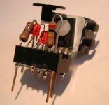
Mhuahahahah....It works!
I have to change the reference resistor to adjust the working point but It works...
Checking the tension and the current through the tube I've seen that I'm near the maximum power dissipation, I'll start right now to change the reference resistor
Thankyou guys...stay tuned
Mark
I have to change the reference resistor to adjust the working point but It works...
Checking the tension and the current through the tube I've seen that I'm near the maximum power dissipation, I'll start right now to change the reference resistor
Thankyou guys...stay tuned
Mark
Hi
Thankyou pedroskova for links and schematics. I'll try to use the 2N2907 for the upper transistor and the zener as voltage reference. Yesterday I've changed the working point and finally I've started to listen. I liked what I've listened. Really! Today anyway I'll take care of the circuit I've made. Some adjustments are required...
1) I'm afraid for the power dissipation of the resistors on the reference chain. They are really hot! I've used two resista 4.5W metal oxide in parallel. The voltage drop is 230V, current settled to 10mA so the power dissipation is something like 2.3W...but they burn anyway! Which is the minimum current for a stable voltage reference using a led? With 4/5mA can do a good job?
2) I've read this:
http://www.magnequest.com/diy_strain.htm
...particulary this:
"There are power resistors on both sides of the 15mA CCS. This is necessary to not overvoltage the MPE350 transistor. It's best to use these between the plate of the 6H30pi and the collector of the MPE350. Here I have them split for build convenience. The MPE350 needs a fairly hefty heatsink to operate safely because it dissipates quite a bit of heat."
It seems that I need the resitor between plate and collector...anyway? With any kind of tube?
3)I've notice that there is a little bit of noise. I've connected the mje350s to the same heatsink ( one heatsink, two mje350) and I've isolated them with mica. When I touch the heatsink the noise increase. Oscillation? I don't know... help me please.
Mark
mark_titano said:
1) I'm afraid for the power dissipation of the resistors on the reference chain. They are really hot! I've used two resista 4.5W metal oxide in parallel. The voltage drop is 230V, current settled to 10mA so the power dissipation is something like 2.3W...but they burn anyway! Which is the minimum current for a stable voltage reference using a led? With 4/5mA can do a good job?
Hi Mark,
With the Bottlehead C4S, the LED's are biased for 2mA. Kurt's looks to be pretty close to that as well.
It seems that I need the resitor between plate and collector...anyway? With any kind of tube?
Here's
a bunch of reasons... by someone who knows a ton more than I do about this electronics stuff.

If you read the rest of the thread, you'll find dissenting opinions.

hope this helps
pedroskova said:
Hi Mark,
With the Bottlehead C4S, the LED's are biased for 2mA. Kurt's looks to be pretty close to that as well.
Here's
a bunch of reasons... by someone who knows a ton more than I do about this electronics stuff.
If you read the rest of the thread, you'll find dissenting opinions.
hope this helps
Hi pedroskova...it will helps, I'm sure...as all your posts

I'll read the 3D eagerly
I've just buy the components to try the schematics at Post #40 .
I'll try to lower the current in my schematics. I've checked the temperature on the components. I've used a simply digutal thermometer: (after one hour)
1) temperature of the heatsink on the mje350s: 68°C
2) irf830 ( power supply): 40°
3) resitor on the reference chain...I don't know, over 75°C, the max temp. that the thermometer support. Temperature had overheated very quick. I suspect that the delta is very high. So much hot...
I suspect that the noise I've heard can be something like thermal noise... It's not as ripple noise or AC interference ( heaters supply is in DC, constant current too...) but like a light breath.
Can it be?
Mark
audiousername said:Bypassing the cathode resistor was probably done to reduce output impedance. Leaving it unbypassed increases the output Z from rp on its own to rp+Rk*(mu+1)
Thankyou for the advice...question: using a ccs load what happen to the output impedance? Using a transistor for example, the fact that the output is connect to the plate and to the collector of the lower transistor does influence the impedance?
If I would use an hybrid mu-follower, like Gary Pimm's one, the answer is YES (...but I don't know how I can calculate it). I don't know for a simple ccs plate load.
Mark
mark_titano said:
And now...what are you doing in Alba? Are you often in Italy?
Ciao Mark
In order: eating white truffles, and about twice a year, more when I can manage it. I work in the wine business so I am fortunate with regard to travelling.
BTW, do be careful about stray capacitances at the plate end of the CCS. That's especially important with heat-sinked transistors.
SY said:Mark, if you have noise that changes when you touch the heatsink, you almost certainly have oscillation. Grid stoppers and work on bypassing will pay dividends.
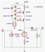
Well this is what I've suspected. Look at the schematic I try...what have I to change? The 100ohm greed stopper is too much low? I try...1K?
Bypassing...the led? I have to increase the 100nF caps?
Do you think that a resitor between plate and colector can helps?
The noise was much high before lowering the current on ccs...
I start to draw a pcb for the schematic posted by pedroskova, I'll post it here as soon as possible
Mark
PS: wine business is a wonderful job... I drink so much wine that I can say I'm in this business too heheheh

A good glass of Morellino di Scansano and a piece of Roquefort and you make me happy
Attachments
SY said:
BTW, do be careful about stray capacitances at the plate end of the CCS. That's especially important with heat-sinked transistors.
Mhmmm... the connection is made by two piece of wire, 1mm, welded on a tagstrip. One piece of wire go to the tube soket, the other one to the ccs board ( wired point to point). Maybe I'd better if I would use only a piece of wire... no?
Mark
I'd go up on the grid stopper (maybe 2k2 to 4k7) and, most important, make sure it's soldered right at the grid, shortest leads possible. Ferrite beads are somewhat black magic- if the 1k base resistors are non-inductive and also soldered close to the bases, the beads probably won't do much. Also, make sure the PS bypassing is close and high quality.
One more thing- you might get rid of those big bypass caps across the LEDs.
In Bergamo tonight. Mmmmm, Branzi.....
One more thing- you might get rid of those big bypass caps across the LEDs.
In Bergamo tonight. Mmmmm, Branzi.....
SY said:I'd go up on the grid stopper (maybe 2k2 to 4k7) and, most important, make sure it's soldered right at the grid, shortest leads possible.
Ok...I'll go with 2k2 first. The 100ohm resistor I've used is close to the grid...so will be the 2k2 one.
SY said:
Ferrite beads are somewhat black magic- if the 1k base resistors are non-inductive and also soldered close to the bases, the beads probably won't do much. Also, make sure the PS bypassing is close and high quality.
1K "base stopper" are carbon resitors...leads shorter than 2mm... At the output of the power supply regulator I've put Two motors cap, 20uF plastic. I'll put two resitors to make an RC filters...and I'll try to make connections shorter. From ccs board to circuit board too. Now wires are 5cm long...I can make them shorter for sure
SY said:
One more thing- you might get rid of those big bypass caps across the LEDs.
About leds...I'll go for a resitor insted the lowers led.
I'll get rid of those caps...thanks
SY said:
In Bergamo tonight. Mmmmm, Branzi.....
Mhmmm....polenta, Branzi and a bottle of Soave Classico...

Well... you can't forget my favourite "Bergamasco" dish!!! "Strangolapreti" are a must!
Mark
Actually, I'd leave in the doubled-up LEDs. The red ones are pretty good voltage sources. IIRC, their source Z is something like 5-10 ohm.
Regarding bypassing, I like to also use a small high frequency cap (like a 100nF polypropylene) from the ground return end of the cathode resistor to point where the B+ feed connects to the CS.
OK, you've got me hungry- off to dinner now. Polenta sounds great. I fly home on Sunday and my suitcase is already packed with rice (carnaroli), flour (tipo fine 00), dried porcini, and polenta flour. And a wee bit of grappa. I love Italy.
Uff...I tried some mods, but buzz is still here.
1)Caps across leds removed.
2)Grid stopper from 100ohm to 1K5 ( I've found some Allen Bradley in my drawer)
3) I've made connection shorter and added a 120ohm resitors between ccs and plate.
4) current in reference chain from 10mA to 4mA ( resitors temperature ok now)
5) I've disconnected the upper transistor from the heatsink
After this mods I've turned on the pre and...noise is higher than it was before.What I've forgot todo was to connect the potentiometer to gnd. However noise is too much high, even if the pot isn't connect to gnd.
Noise come in in the signal path between pot and grid, I suspect. If I disconnect the shield on the cable, noise increase even if I approach my hand near the cable!
Can be a ground loop problem? Oscillation indeed, but which can be the reason? The ccs?
Well...I'll go for a 4K7 grid stopper, good shield cable and small bypass as SY said.
Please advice me if I need to check something.
Mark
PS: SY...have you tasted "polenta and Branzi"?
- Status
- This old topic is closed. If you want to reopen this topic, contact a moderator using the "Report Post" button.
- Home
- Amplifiers
- Tubes / Valves
- 5687 and ccs?