Hi Mark
Brett's one is a perfect explanation.
I only add a point.
Some times the input resistance of the following
stage is not so high.
I saw SS amp with input resistance lower that 10k Ohm.
In any case, to avoid mistakes, it is always better ( and correct)
to consider the parallel of anode load and input res
of following stage.
The current is constant in the CCS not in the tube.
Ciao
Federico
Brett's one is a perfect explanation.
I only add a point.
Some times the input resistance of the following
stage is not so high.
I saw SS amp with input resistance lower that 10k Ohm.
In any case, to avoid mistakes, it is always better ( and correct)
to consider the parallel of anode load and input res
of following stage.
what I thought is that, if the current is constant ...
The current is constant in the CCS not in the tube.
Ciao
Federico
Thankyou very much to all of you.
I've read the Gary Pimm's article with more attention. I've trascured some things.
Gary suggest to use a mu follower output and write:
"It is interesting to note that only the circuits using the mu output have the triode operating in true constant current mode. In the other variations of CCS loaded triodes where the signal is taken from the plate, the plate current varies in proportion with the load current."
Now, I will take the SY circuit as an example. If I'm right, I can't do a mu follower output using a PNP transistor in the ccs load. In this case I have to take the output from the plate. The solution seems to use a NPN transistor, but, if I use a led to polarise it, I'll have current that flow from the reference chain to the plate and this is a bad thing ( thankyou Ec8010 )
Maybe I can use a special led like this or maybe i can polarize the transistor with a battery, like Pimm do with his mosfet cascode.
http://www.fairchildsemi.com/ds/HL/HLMP-K150.pdf
Mu follower or simple plate output? Battery or special led? I like to know your "Guru opinion" about these different possibilities, maybe with an explanation of your chosen
Hi, Mark
I've read the Gary Pimm's article with more attention. I've trascured some things.
Gary suggest to use a mu follower output and write:
"It is interesting to note that only the circuits using the mu output have the triode operating in true constant current mode. In the other variations of CCS loaded triodes where the signal is taken from the plate, the plate current varies in proportion with the load current."
Now, I will take the SY circuit as an example. If I'm right, I can't do a mu follower output using a PNP transistor in the ccs load. In this case I have to take the output from the plate.
The solution seems to use a NPN transistor, but, if I use a led to polarise it, I'll have current that flow from the reference chain to the plate and this is a bad thing ( thankyou Ec8010 )Maybe I can use a special led like this or maybe i can polarize the transistor with a battery, like Pimm do with his mosfet cascode.
http://www.fairchildsemi.com/ds/HL/HLMP-K150.pdf
Mu follower or simple plate output? Battery or special led? I like to know your "Guru opinion" about these different possibilities, maybe with an explanation of your chosen
Hi, Mark
Just my biased opinion, but I think you're very quickly at the point where the tube nonlinearities dominate the circuit performance. If you're interested in playing around with optimizing the blocks within the circuit for its own sake, by all means try out some of the fancier mu follower implementations. But the simple bipolar cascode I used resulted in a circuit that gave essentially the same performance as Morgan Jones's mu follower version.
Today I start to do my homeworks
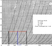
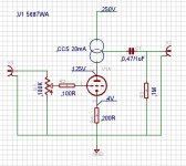
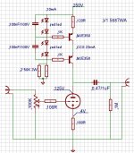
I look the graphics to find the working point for the 5687.
I attach the working point I choose...what do you think?
If I'll be able to make the tube work in constant current mode, the distortion will be very low. The max plate dissipation is 3.75W for each section, with 2.4W I think I can be comfortable .
I look the graphics to find the working point for the 5687.
I attach the working point I choose...what do you think?
If I'll be able to make the tube work in constant current mode, the distortion will be very low. The max plate dissipation is 3.75W for each section, with 2.4W I think I can be comfortable
.Attachments
Hi Federico, tomorrow I'll start to looking for the component I need.
For the ccd I'll try this one:
http://www.pacifier.com/~gpimm/Battery_biased_ccs.htm
I see what kind of battery I'll find and then I'll optimize the circuit.
How does it looks?
You can see the performance here...impressive...
http://www.pacifier.com/~gpimm/ccs_performance.htm
Something similar here...
http://home.zonnet.nl/horneman/mosfet.htm
Hi...I need an opinion. I find all the component to make the Pimm's CCS...
http://www.pacifier.com/~gpimm/Battery_biased_ccs.htm
...except the mos. I've found the IRF830 instead the 820, do you think can works? Except the modify of R1 ( I haven't read the datasheet, I'm not sure that the turn-on voltage is the same) can have I other problems? About the shunt capacitance? Can I calculate it or the only solution is test it?
I've bought 4 Mje 350 I want to try something like this in cascode mode too
http://www.machmat.com/sales/kits/images/ccscir.gif
What do you think? I'll post the schematic tomorrow when I'll be at home and I'll can use eagle
Mark
CCS + 12B4G
I'm late to the party, but:
I use this very combination - A 12B4G, loaded with the depletion-mode mosfet CCS shown in post #10.
I build the CCS with the mosfets back-to-back on a heatsink (use mica!) I don't recall the exact resistor values, but it's running 12 mA.
I like it, but the 12B4Gs tend to be microphonic. Prod me and I'll dredge up values and photos.
mark_titano said:
Well, I'll try with a simple depletion mode mosfet. Something like this can work well?
I'm late to the party, but:
I use this very combination - A 12B4G, loaded with the depletion-mode mosfet CCS shown in post #10.
I build the CCS with the mosfets back-to-back on a heatsink (use mica!) I don't recall the exact resistor values, but it's running 12 mA.
I like it, but the 12B4Gs tend to be microphonic. Prod me and I'll dredge up values and photos.
Re: CCS + 12B4G
Thankyou Andy... photos please! For the value doesn't matter, I see the circuit to find R values
My doubt remains for the battery ccs...I think using the irf830 instead the 820 can work but I need help from the GURUS
The Vgs seems to be the same ( from 2 to 4V, typ 3V). Imput and output capacitance is double, I don't know if this can create instability. I suspect the right answer is "no" but I like your opinion before do something wrong.
M
AndyN said:
I'm late to the party, but:
I use this very combination - A 12B4G, loaded with the depletion-mode mosfet CCS shown in post #10.
I build the CCS with the mosfets back-to-back on a heatsink (use mica!) I don't recall the exact resistor values, but it's running 12 mA.
I like it, but the 12B4Gs tend to be microphonic. Prod me and I'll dredge up values and photos.
Thankyou Andy... photos please! For the value doesn't matter, I see the circuit to find R values
My doubt remains for the battery ccs...I think using the irf830 instead the 820 can work but I need help from the GURUS
The Vgs seems to be the same ( from 2 to 4V, typ 3V). Imput and output capacitance is double, I don't know if this can create instability. I suspect the right answer is "no" but I like your opinion before do something wrong.
M
And now the MJE350 cascode...
My doubts:
1) in the datasheet I see that the Hfe is from 30 to 240...how can I calculate it precisely? In the datasheet there is an dc current gain graf, but it seems that the curves are plot in function of Tj,Ic and Vce.... too many unknowns for the poor documentations in the datasheet.... However,the plate have to see a load as greater as possible, right? To do this the resistor in front of the first MJE have to be greater as possible...so the voltage across it have to be the greater as possible. How much this voltage can be high? I can obtain it putting in series two or three led. For a mosfet there is a limit for the Vgs ( 20V). For a transistor exists a limit for the Vbe???
2)Instead the resistor on the base can be a good solution if I'll use a ferrite bean? This can limitate the oscillation in RF perhaps...
3) the current in the reference chain is too much high for a 1.65V drop? With 10mA the Ib isn't a problem indeed....
Attachments
Re: another guy from Padova!
Ciao Paolo, thankyou very much for your advice
I'll do it, I start immediatly to draw the pcb
Grazie ancora
Mark
pamaz said:Ciao Mark
AFAIK no problems are foreseen in using an 830 instead an 820. especially if you're wiring your first rig for this amp. Moving to an 820 could be a choice that you can always do later if there is an appreciable sonic benefit.
Ciao
Paolo
Ciao Paolo, thankyou very much for your advice
I'll do it, I start immediatly to draw the pcb
Grazie ancora
Mark
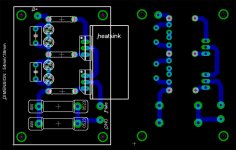
This is the fist bord for the "ccs MJE350 cascode". This is my third pcb, I've read some articles about the design rules but, once again, I have not experience... If it looks good I can post the eagles file... I hope this can helps those who wants to try something like this. And now I start to draw the mosfet ccs board.
In the board I've drew two led to polarize the transistor, the values in the schematics at post33# are for a single led
Mark
I hope this can helps those who wants to try something like this. And now I start to draw the mosfet ccs board.In the board I've drew two led to polarize the transistor, the values in the schematics at post33# are for a single led
Mark
Attachments
Re: Re: CCS + 12B4G
I'm certainly not a guru - I just follow the recipie I cannot comment on your irf830 design, I'm not wise enough.
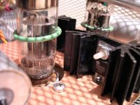
I'm using Siliconix DN2540 mosfets - no biasing batteries needed. It may not be apparent in the photo, but they are physically supported by the heat sink, with one mostfet on each side. The legs of the chips hang down and I tie 1/4 resistors on, BEAM-style. The rest is wired point to point.
Be aware that the glass of the 12B4G runs relatively hot. Radiant heat from the big filament current, I think.
Cheers, Andy
mark_titano said:My doubt remains for the battery ccs...I think using the irf830 instead the 820 can work but I need help from the GURUS
M
I'm certainly not a guru - I just follow the recipie
I cannot comment on your irf830 design, I'm not wise enough.I'm using Siliconix DN2540 mosfets - no biasing batteries needed. It may not be apparent in the photo, but they are physically supported by the heat sink, with one mostfet on each side. The legs of the chips hang down and I tie 1/4 resistors on, BEAM-style. The rest is wired point to point.
Be aware that the glass of the 12B4G runs relatively hot. Radiant heat from the big filament current, I think.
Cheers, Andy
Attachments
Andy good work! Can you tell me how change the sound using a ccs load instead a R load? Your impression indeed...
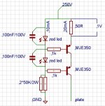
I start to make the version with the mje350 ( I can't try a mufollower output but I want to start with the simpler circuit just to understand how it works). I'm only waiting that someone comments my design...here the new schematic
Mark
I start to make the version with the mje350 ( I can't try a mufollower output but I want to start with the simpler circuit just to understand how it works). I'm only waiting that someone comments my design...here the new schematic
Mark
Attachments
Hi pedroskova, thankyou for the schematic.
This my first DIM ("do it myself") attempt, so, nice to see I'm not far from others solutions
I'll look for the LM329 and bc327 datasheets, I don't know them.
I suspect that the Lm329 is a 7V zener...infact to have 20mA trow R=R5+R3=320R I need something like 6.4V ( for a transistor I assume a Vbe=0.65V).The oscon cap is there to limitate the noise...obviously I'm not sure at all, in this moment I'm only an apprentice
What I don't understand is R10. Why do I need it there? To prevent oscillations? Doesn't create non-linearity to the load? When I have a voltage drop in the tube, the resistor doesn't make the current stability across the tube worse? This is only a question, not my point of view, I've never try something similar, I only want to understand
Mark
This my first DIM ("do it myself"
) attempt, so, nice to see I'm not far from others solutions I'll look for the LM329 and bc327 datasheets, I don't know them.
I suspect that the Lm329 is a 7V zener...infact to have 20mA trow R=R5+R3=320R I need something like 6.4V ( for a transistor I assume a Vbe=0.65V).The oscon cap is there to limitate the noise...obviously I'm not sure at all, in this moment I'm only an apprentice
What I don't understand is R10. Why do I need it there? To prevent oscillations? Doesn't create non-linearity to the load? When I have a voltage drop in the tube, the resistor doesn't make the current stability across the tube worse? This is only a question, not my point of view, I've never try something similar, I only want to understand
Mark
mark_titano said:
What I don't understand is R10. Why do I need it there? To prevent oscillations? Doesn't create non-linearity to the load? When I have a voltage drop in the tube, the resistor doesn't make the current stability across the tube worse? This is only a question, not my point of view, I've never try something similar, I only want to understand
Mark
Actually, I don't know what it does.
 I just use the basic C4S without the added diode, cap, and resistor.
Just to muddy up the waters further,
here's another variation and discussion from Kurt Strain
This is the image he's referring to.An externally hosted image should be here but it was not working when we last tested it.
- Status
- This old topic is closed. If you want to reopen this topic, contact a moderator using the "Report Post" button.
- Home
- Amplifiers
- Tubes / Valves
- 5687 and ccs?