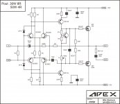
Not my design, OP amp driven input.Input impedance: 220 ohm, hope it's driven from another power amplifier
Or maybe you should consider using the non-inverting input ?
Soren
It is unusual, not my design. Quadral use similar design but with three pair mosfet on +/-90V.Mile , there some mistakes on the schematic..
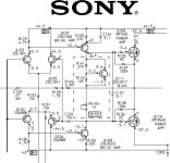

Amplifier based on Sony schematics.
50/100W 4/2R (20Hz-20kHz, 0,04% THD)
5Hz-50kHz +0,5/-3dB
THD 0,005% (1kHz, 4R)
I reckon you could get 300watts peak with a higher voltage rail.
If the MOSFET's are 150w and they only conduct on half cycles then that is 300watts per half cycle each MOSFET can stand.
First thing interesting to me when I see Sony schematics is useing IRF540/IRF9540 in fully simetry design, and low THD. It's good circuit for playing and experiment.I reckon you could get 300watts peak with a higher voltage rail.
If the MOSFET's are 150w and they only conduct on half cycles then that is 300watts per half cycle each MOSFET can stand.
Quadral use higher value for feedback resistor to get higher input impedanse, or will be better to use noninverting input? Can this simple circuit have Sonys figures? It's remande me on Hafler preamp DH101.
If you can live with an input impedance that low then using the inverting input can improve distorsion figures a bit. This is because the input transistors operate close to current controlled rather than voltage controlled.
But I don´t think this would be more than just measurable. On the other hand, lowering the values of the feedback resistors would improve speed and stability.
Also, I would add identical resistors to the two input transistors where the collectors are tied to the supply rails now.
Then, add an extra VAS transistor between the new resistors and the current VAS emitter. The "new" collectors should be grounded. This way, the VAS operates fully differential and distorsion is likely to drop significantly!
")
Like this?If you can live with an input impedance that low then using the inverting input can improve distorsion figures a bit. This is because the input transistors operate close to current controlled rather than voltage controlled.
But I don´t think this would be more than just measurable. On the other hand, lowering the values of the feedback resistors would improve speed and stability.
Also, I would add identical resistors to the two input transistors where the collectors are tied to the supply rails now.
Then, add an extra VAS transistor between the new resistors and the current VAS emitter. The "new" collectors should be grounded. This way, the VAS operates fully differential and distorsion is likely to drop significantly!
Attachments
Then, add an extra VAS transistor between the new resistors and the current VAS emitter. The "new" collectors should be grounded. This way, the VAS operates fully differential and distorsion is likely to drop significantly!
I once tested this configuration, but unfortenately,
it didn t worked according to my expectations.
Did you manage to obtain good results in your tries?..
Yes, like that but remove the capacitor across one of the emitter resistors. Also, remember that the current through each VAS transistor will be reduced, so this may have to be compensated for by decreasing the emitter resistor values, or increase the input differential collector resistors slightly. Have you tried simulating it?
I once tested this configuration, but unfortenately,
it didn t worked according to my expectations.
Did you manage to obtain good results in your tries?..
Why? What happened?
Why? What happened?
Well, nothing happned, if i can say so.
Distorsion figures didn t improve, stability was no better, and so on,
so i reverted to the classical Vas scheme.
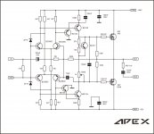
Here the definitive implementation, that is, the generic one,
although i use a mosfet version that is quite good , but not
substancially better than the BJTs one , since bipolar power
devices are currently of good global perfs.
http://www.diyaudio.com/forums/solid-state/155993-awb50-simple-power-amp.html
Last edited:
Marfy law for electronic?Well, nothing happned, if i can say so.
Distorsion figures didn t improve, stability was no better, and so on,
so i reverted to the classical Vas scheme.
Here the definitive implementation, that is, the generic one,
although i use a mosfet version that is quite good , but not
substancially better than the BJTs one , since bipolar power
devices are currently of good global perfs.
http://www.diyaudio.com/forums/solid-state/155993-awb50-simple-power-amp.html
Nice simple amp that no doubt will perform without any problems wahab
The thing i see looking at the circuit with the differential as the Vas is a total lack of emitter degeneration resistors. That would be on the input LTP & the Vas. That will seriously mess with the linearity. There is also the likelyhood of the Vas going into operation in class B with no emitter degeneration, yes it still could with degeneration - but it'd be far less likely. As it is the open loop gain must be rather high
I prefer some local feedback rather than loads of global feedback, but each to there own
Banned
Joined 2002
PCB can be 60x40mm, smaler than TDA7294Looks simple!
- Status
- This old topic is closed. If you want to reopen this topic, contact a moderator using the "Report Post" button.
- Home
- Amplifiers
- Solid State
- 50W mosfet amplifier IRF540/IRF9540