At first it might look differential, but really just a complimentary
pair of error correcting amps. Same basic game plan as Allison.
Just another goofy way to do it.... Creating as many mysteries
as it seems to solve...
The quasi complimentary pairs don't balance with equal resistors,
and I'm not sure why that is? Also the push and pull phases don't
want to stay together at 96KHz unless I cripple the N-JFETs with
extra Miller... I'm assuming that dumbs em down to better match
the speed of the P's?
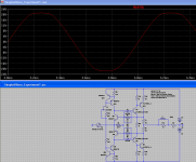
It behaves well under duress (absurd voltage / slew) on the sim.
But 1W distortion is nothing special... At least loop bandwidth is
up where TIM shouldn't be an issue...
Pretty close to both rails, considering no bootstrappage abused.
Unfortunately without strappage, voltage clipping isn't softened...
I'm not sure I've improved on anything over previous attempts.
Just so you know I haven't dropped off the face of the planet.
I still follow this thread, and want to know about your progress.
Still need your custom .models to follow along with your design.
Can you zip those up with an .ASC every once in a while?
pair of error correcting amps. Same basic game plan as Allison.
Just another goofy way to do it.... Creating as many mysteries
as it seems to solve...
The quasi complimentary pairs don't balance with equal resistors,
and I'm not sure why that is? Also the push and pull phases don't
want to stay together at 96KHz unless I cripple the N-JFETs with
extra Miller... I'm assuming that dumbs em down to better match
the speed of the P's?
It behaves well under duress (absurd voltage / slew) on the sim.
But 1W distortion is nothing special... At least loop bandwidth is
up where TIM shouldn't be an issue...
Pretty close to both rails, considering no bootstrappage abused.
Unfortunately without strappage, voltage clipping isn't softened...
I'm not sure I've improved on anything over previous attempts.
Just so you know I haven't dropped off the face of the planet.
I still follow this thread, and want to know about your progress.
Still need your custom .models to follow along with your design.
Can you zip those up with an .ASC every once in a while?
Attachments
Following my own advice....
Here are the .ASC and .models for my above drawing.
Anyone know where I can find MJE340/350 as BJT .models?
I do already have them as .subckts.... Wanna try them as
drivers for these final outputs... I just seem to lack .models
for anything complimentary throughole in medium Wattage.
Small and big BJT models I got. Medium, still an information
vacuum..
Attachments
x-feed r-c network
H Ken,
Does your allson require x-feed network (c5-r25/c6-r26) like this one? (post 97)
http://www.diyaudio.com/forums/showthread.php?s=&threadid=96853&perpage=25&pagenumber=4
Regards,
atiq
H Ken,
Does your allson require x-feed network (c5-r25/c6-r26) like this one? (post 97)
http://www.diyaudio.com/forums/showthread.php?s=&threadid=96853&perpage=25&pagenumber=4
Regards,
atiq
Attachments
kenpeter said:At first it might look differential, but really just a complimentary
pair of error correcting amps. Same basic game plan as Allison.
Just another goofy way to do it.... Creating as many mysteries
as it seems to solve...
The quasi complimentary pairs don't balance with equal resistors,
and I'm not sure why that is? Also the push and pull phases don't
want to stay together at 96KHz unless I cripple the N-JFETs with
extra Miller... I'm assuming that dumbs em down to better match
the speed of the P's?
It behaves well under duress (absurd voltage / slew) on the sim.
But 1W distortion is nothing special... At least loop bandwidth is
up where TIM shouldn't be an issue...
Pretty close to both rails, considering no bootstrappage abused.
Unfortunately without strappage, voltage clipping isn't softened...
I'm not sure I've improved on anything over previous attempts.
Just so you know I haven't dropped off the face of the planet.
I still follow this thread, and want to know about your progress.
Still need your custom .models to follow along with your design.
Can you zip those up with an .ASC every once in a while?
That is very unique. I was looking for a way to implement the Allison with common-collector outputs. Although this is probably far from what Allison himself envisioned. I have a feeling you would get much better overall performance if you could replace the FETs with BJTs.
I haven't dropped off the face of the planet either, but I haven't had any news since I discovered I didn't have any suitable transistors for the supply voltages I'm using. So until I get an order of BCxxx transistors, I won't have anything more to report.
Since you ask, I'll zip up all of the Allison derivations I've posted and attach it. The Allison+LTP schematic I included is more advanced I think than I have shown here, and the extra components can be done without I think, but I don't have the time to dumb it down again.
kenpeter said:Following my own advice....
Here are the .ASC and .models for my above drawing.
Anyone know where I can find MJE340/350 as BJT .models?
I do already have them as .subckts.... Wanna try them as
drivers for these final outputs... I just seem to lack .models
for anything complimentary throughole in medium Wattage.
Small and big BJT models I got. Medium, still an information
vacuum..
Here are the models I have been using:
These ones are probably not very good. I think I got them from ONsemi.
.MODEL Qmje340 npn IS=1.03431e-13 BF=172.974 NF=0.939811 VAF=27.3487 IKF=0.0260146 ISE=4.48447e-11 NE=1.61605 BR=16.6725 NR=0.796984 VAR=6.11596 IKR=0.10004 ISC=9.99914e-14 NC=1.99995 RB=1.47761 IRB=0.2 RBM=1.47761 RE=0.0001 RC=1.42228 XTB=2.70726 XTI=1 EG=1.206 CJE=1e-11 VJE=0.75 MJE=0.33 TF=1e-09 XTF=1 VTF=10 ITF=0.01 CJC=1e-11 VJC=0.75 MJC=0.33 XCJC=0.9 FC=0.5 CJS=0 VJS=0.75 MJS=0.5 TR=1e-07 PTF=0 KF=0 AF=1 Vceo=300 Icrating=500m mfg=STMicro
.MODEL Qmje350 pnp IS=6.01619e-15 BF=157.387 NF=0.910131 VAF=23.273 IKF=0.0564808 ISE=4.48479e-12 NE=1.58557 BR=0.1 NR=1.03823 VAR=4.14543 IKR=0.0999978 ISC=1.00199e-13 NC=1.98851 RB=0.1 IRB=0.202965 RBM=0.1 RE=0.0710678 RC=0.355339 XTB=1.03638 XTI=3.8424 EG=1.206 CJE=1e-11 VJE=0.75 MJE=0.33 TF=1e-09 XTF=1 VTF=10 ITF=0.01 CJC=1e-11 VJC=0.75 MJC=0.33 XCJC=0.9 FC=0.5 CJS=0 VJS=0.75 MJS=0.5 TR=1e-07 PTF=0 KF=0 AF=1 Vceo=300 Icrating=500m mfg=STMicro
These were made by Andy_C, so they should be almost (if not) perfect:
.MODEL mjl3281a_x npn IS=9.8145e-12 BF=438.0 NF=1.00 VAF=38 IKF=19.0 ISE=1.0e-12 NE=1.1237388682 BR=4.98985 NR=1.09511 VAR=4.32026 IKR=4.37516 ISC=3.25e-13 NC=3.96875 RB=3.997 RE=0.00 RC=0.06 XTB=0.115253 XTI=1.03146 EG=1.11986 CJE=1.144e-08 VJE=0.468574 MJE=0.34957 TF=2.6769e-9 XTF=7500 VTF=3.0 ITF=1000 CJC=1.093685e-9 VJC=0.623643 MJC=0.482111 XCJC=0.959922 FC=0.1 CJS=0 VJS=0.75 MJS=0.5 TR=1e-07 PTF=0 KF=0 AF=1 Vceo=200 Icrating=15 mfg=OnSemiconductor
.MODEL mjl1302a_x pnp IS=9.8145e-12 BF=122.925 NF=1.00 VAF=40 IKF=19 ISE=9.18577762370362E-07 NE=5.0 BR=4.98985 NR=1.09511 VAR=4.32026 IKR=4.37516 ISC=3.25e-13 NC=3.96875 RB=3.30 RE=0.00 RC=0.06 XTB=0.115253 XTI=1.03146 EG=1.11986 CJE=1.561e-08 VJE=0.781803 MJE=0.433868 TF=3.257e-9 XTF=1000 VTF=2.0 ITF=260 CJC=2.346838e-9 VJC=0.27876 MJC=0.411324 XCJC=0.959922 FC=0.1 CJS=0 VJS=0.75 MJS=0.5 TR=1e-07 PTF=0 KF=0 AF=1 Vceo=200 Icrating=15 mfg=OnSemiconductor
.MODEL Q2SA1837_x PNP ( IS=2.39372559E-10 NF=1.304015937 BF=300 VAF=273 IKF=2.087725944 NK=0.94719458 ISE=1.46829699E-11 NE=1.526663542 BR=4 NR=1 VAR=20 IKR=1.05 RE=0 RB=1.8 RC=1.65 CJE=4.7407E-10 VJE=1.1 MJE=0.5 CJC=8.6700E-11 VJC=0.3 MJC=0.3 TF=1.642191E-09 FC=0.5 ITF=1.076260106 XTF=5.868994022 TR=1.38U)
.MODEL Q2SC4793_x NPN ( IS=1.8E-09 NF=1.43 BF=146.38 VAF=273 IKF=2.6 NK=0.95 ISE=6.286997E-10 NE=2.223629 BR=4 NR=1 VAR=20 IKR=1.05 RE=0 RB=1.7 RC=1.25 CJE=5.96964E-10 VJE=1.1 MJE=0.5 CJC=5.78E-11 VJC=0.3 MJC=0.3 TF=1.22678E-09 FC=0.5 ITF=10 XTF=99.52253015 TR=983N)
Christer, of course. These are short, maybe they don't model everything, but they are the only models of these devices I know of.
.model 2SD669_Christer NPN (IS=5p NF=1 BF=250 ISE=5p NE=1.5 IKF=3 VAF=150 RB=1 RC=0.25 RE=0.25 TF=1.14ns CJC=50p )
.model 2SB649_Christer PNP (IS=5p NF=1 BF=250 ISE=10p NE=1.5 IKF=3 VAF=75 RB=1 RC=0.25 RE=0.25 TF=1.14ns CJC=50p )
These were made by Syn08:
.MODEL Q2SA1407_syn08 PNP ( IS=15.2F NF=1 BF=416 VAF=254 IKF=90M ISE=3.66P NE=2 BR=4 NR=1 VAR=20 IKR=.135 RE=7.63 RB=30.5 RC=3.05 XTB=1.5 CJE=22P VJE=1.1 MJE=.5 CJC=7.1P VJC=.3 MJC=.3 TF=397P TR=276N)
.MODEL Q2SC3601_syn08 NPN ( IS=15.2F NF=1 BF=416 VAF=254 IKF=90M ISE=3.66P NE=2 BR=4 NR=1 VAR=20 IKR=.135 RE=5.63 RB=22.5 RC=2.25 XTB=1.5 CJE=18.3P VJE=1.1 MJE=.5 CJC=5.91P VJC=.3 MJC=.3 TF=397P TR=276N)
.MODEL Q2SA1930_syn08 PNP( IS=10.000E-15 BF=210 VAF=78 IKF=10.000E-3 XTB=1.5 BR=.1001 VAR=100 IKR=10.000E-3 ISC=10.000E-15 CJE=3.252E-12 CJC=63.196E-12 MJC=.33333 TF=83.239E-12 XTF=10 VTF=10 ITF=1)
.MODEL Q2SC5171_syn08 NPN( IS=10.000E-15 BF=210 VAF=100 IKF=10.000E-3 XTB=1.5 BR=.1001 VAR=100 IKR=10.000E-3 ISC=10.000E-15 CJE=2.0000E-12 CJC=38.866E-12 MJC=.33333 TF=83.239E-12 XTF=10 VTF=10 ITF=1)
These should treat you well.
Live well,
- keantoken
Attachments
Re: x-feed r-c network
My Allison of Post 97??? I didn't post 97, nor does it seem to
have any schematic attached, so I'm not sure which drawing
we are talking about? I will use your latest drawing for the
purpose of reference designators in my response.
Some degeneration of the error correction does seem necessary.
Especially when we deal with inputs and/or outputs that exceed
saturation and/or cutoff voltage boundaries... Those drive signals
will leap away at maximum slew, when there is no other feedback
but an output that can no further move to prevent it.
I would have put resistors parallel with D1 & D2. That the
collectors have some linearizing negative feedback to bases...
This also creates small voltage drops across R17 & R18, which
can be simultaneously abused for bias tweaking purposes.
Your D5, D6, and the associated CCS might not be needed.
D1 and D2 might be chosen to have a breakdown voltage just
above that needed to fully saturate the next stage... That too
could help prevent drive signal overshoot.
I'm not sure what your C5 + R25 are supposed to be doing?
I'll try that, and see what happens... Whats with the glitch we
see in I(R11)? Was that a drive signal overshoot, or the tail of
a bipolar coming out of saturation?
atiq19 said:H Ken,
Does your allson require x-feed network (c5-r25/c6-r26) like this one? (post 97)
http://www.diyaudio.com/forums/showthread.php?s=&threadid=96853&perpage=25&pagenumber=4
Regards,
atiq
My Allison of Post 97??? I didn't post 97, nor does it seem to
have any schematic attached, so I'm not sure which drawing
we are talking about? I will use your latest drawing for the
purpose of reference designators in my response.
Some degeneration of the error correction does seem necessary.
Especially when we deal with inputs and/or outputs that exceed
saturation and/or cutoff voltage boundaries... Those drive signals
will leap away at maximum slew, when there is no other feedback
but an output that can no further move to prevent it.
I would have put resistors parallel with D1 & D2. That the
collectors have some linearizing negative feedback to bases...
This also creates small voltage drops across R17 & R18, which
can be simultaneously abused for bias tweaking purposes.
Your D5, D6, and the associated CCS might not be needed.
D1 and D2 might be chosen to have a breakdown voltage just
above that needed to fully saturate the next stage... That too
could help prevent drive signal overshoot.
I'm not sure what your C5 + R25 are supposed to be doing?
I'll try that, and see what happens... Whats with the glitch we
see in I(R11)? Was that a drive signal overshoot, or the tail of
a bipolar coming out of saturation?
Ah. OK.
I don't know if these models are accurate enough to be used for what people use LEDs for in audio, but I'm fairly sure the transistor models are accurate.
.model J2sk246 NJF(Beta=1.07m Rs=56.76 Rd=56.76 Betatce=-.5 Lambda=2.8m
+ Vto=-2.638 Vtotc=-2.5m Cgd=10.38p M=.4373 Pb=.3905 Fc=.5
+ Cgs=6.043p Isr=112.8p Nr=2 Is=11.28p N=1 Xti=3 Alpha=10u Vk=100
+ Kf=1E-18 Af=1)
.model J2sj103 PJF(Beta=2.197m Rs=76.76 Rd=76.76 Betatce=-.5 Lambda=735.3u
+ Vto=-2.037 Vtotc=-2.5m Cgd=18.95p M=.5045 Pb=.3905 Fc=.5
+ Cgs=17.02p Isr=38.48f Nr=2 Is=3.848f N=1 Xti=3 Alpha=10u Vk=100
+ Kf=1E-18 Af=1)
.model J2sk108 NJF(Beta=28.33m Rs=14.67 Rd=14.67 Betatce=-.5 Lambda=2.273m
+ Vto=-.6597 Vtotc=-2.5m Cgd=1p M=.3333 Pb=1 Fc=.5 Cgs=19.55p
+ Isr=154.3p Nr=2 Is=15.43p N=1 Xti=3 Alpha=10u Vk=100 Kf=1E-18
+ Af=1)
.model J2sk370 NJF(Beta=62.95m Rs=4.733 Rd=4.733 Betatce=-.5 Lambda=1.19m
+ Vto=-.4562 Vtotc=-2.5m Cgd=23.16p M=.3938 Pb=.3905 Fc=.5
+ Cgs=23.61p Isr=86.47p Nr=2 Is=8.647p N=1 Xti=3 Alpha=10u Vk=100
+ Kf=55.11E-18 Af=1)
.model J2sk170 NJF(Beta=59.86m Rs=4.151 Rd=4.151 Betatce=-.5 Lambda=1.923m
+ Vto=-.5024 Vtotc=-2.5m Cgd=20p M=.3805 Pb=.4746 Fc=.5
+ Cgs=25.48p Isr=84.77p Nr=2 Is=8.477p N=1 Xti=3 Alpha=10u Vk=100
+ Kf=111.3E-18 Af=1)
.model J2sj74 PJF(Beta=92.12m Rs=7.748 Rd=7.748 Betatce=-.5 Lambda=4.464m
+ Vto=-.5428 Vtotc=-2.5m Cgd=85.67p M=.3246 Pb=.3905 Fc=.5
+ Cgs=78.27p Isr=129.8p Nr=2 Is=12.98p N=1 Xti=3 Alpha=10u Vk=100
+ Kf=26.64E-18 Af=1)
.model MPSA18 NPN(Is=33.58f Xti=3 Eg=1.11 Vaf=100 Bf=2.365K Ne=1.579 Ise=166.7f Ikf=.1172 Xtb=1.5 Br=5.774 Nc=2 Isc=0 Ikr=0 Rc=1 Cjc=4.948p Mjc=.4109 Vjc=.75 Fc=.5 Cje=7.547p Mje=.3765 Vje=.75 Tr=800.3p Tf=310.1p Itf=.6 Vtf=6 Xtf=35 Rb=10)
.MODEL LED_RED D (IS=93.2P RS=42M N=3.73 BV=4 IBV=10U CJO=2.97P VJ=.75 M=.333 TT=4.32U type=LED)
.MODEL LED D (IS=93.1P RS=42M N=4.61 BV=4 IBV=10U CJO=2.97P VJ=.75 M=.333 TT=4.32U type=LED)
.MODEL LED_Blue D (IS=93.1P RS=42M N=7.47 BV=5 IBV=30U CJO=2.97P VJ=.75 M=.333 TT=4.32U type=LED)
I can easily add a voltage drop resistor.
- keantoken
I don't know if these models are accurate enough to be used for what people use LEDs for in audio, but I'm fairly sure the transistor models are accurate.
.model J2sk246 NJF(Beta=1.07m Rs=56.76 Rd=56.76 Betatce=-.5 Lambda=2.8m
+ Vto=-2.638 Vtotc=-2.5m Cgd=10.38p M=.4373 Pb=.3905 Fc=.5
+ Cgs=6.043p Isr=112.8p Nr=2 Is=11.28p N=1 Xti=3 Alpha=10u Vk=100
+ Kf=1E-18 Af=1)
.model J2sj103 PJF(Beta=2.197m Rs=76.76 Rd=76.76 Betatce=-.5 Lambda=735.3u
+ Vto=-2.037 Vtotc=-2.5m Cgd=18.95p M=.5045 Pb=.3905 Fc=.5
+ Cgs=17.02p Isr=38.48f Nr=2 Is=3.848f N=1 Xti=3 Alpha=10u Vk=100
+ Kf=1E-18 Af=1)
.model J2sk108 NJF(Beta=28.33m Rs=14.67 Rd=14.67 Betatce=-.5 Lambda=2.273m
+ Vto=-.6597 Vtotc=-2.5m Cgd=1p M=.3333 Pb=1 Fc=.5 Cgs=19.55p
+ Isr=154.3p Nr=2 Is=15.43p N=1 Xti=3 Alpha=10u Vk=100 Kf=1E-18
+ Af=1)
.model J2sk370 NJF(Beta=62.95m Rs=4.733 Rd=4.733 Betatce=-.5 Lambda=1.19m
+ Vto=-.4562 Vtotc=-2.5m Cgd=23.16p M=.3938 Pb=.3905 Fc=.5
+ Cgs=23.61p Isr=86.47p Nr=2 Is=8.647p N=1 Xti=3 Alpha=10u Vk=100
+ Kf=55.11E-18 Af=1)
.model J2sk170 NJF(Beta=59.86m Rs=4.151 Rd=4.151 Betatce=-.5 Lambda=1.923m
+ Vto=-.5024 Vtotc=-2.5m Cgd=20p M=.3805 Pb=.4746 Fc=.5
+ Cgs=25.48p Isr=84.77p Nr=2 Is=8.477p N=1 Xti=3 Alpha=10u Vk=100
+ Kf=111.3E-18 Af=1)
.model J2sj74 PJF(Beta=92.12m Rs=7.748 Rd=7.748 Betatce=-.5 Lambda=4.464m
+ Vto=-.5428 Vtotc=-2.5m Cgd=85.67p M=.3246 Pb=.3905 Fc=.5
+ Cgs=78.27p Isr=129.8p Nr=2 Is=12.98p N=1 Xti=3 Alpha=10u Vk=100
+ Kf=26.64E-18 Af=1)
.model MPSA18 NPN(Is=33.58f Xti=3 Eg=1.11 Vaf=100 Bf=2.365K Ne=1.579 Ise=166.7f Ikf=.1172 Xtb=1.5 Br=5.774 Nc=2 Isc=0 Ikr=0 Rc=1 Cjc=4.948p Mjc=.4109 Vjc=.75 Fc=.5 Cje=7.547p Mje=.3765 Vje=.75 Tr=800.3p Tf=310.1p Itf=.6 Vtf=6 Xtf=35 Rb=10)
.MODEL LED_RED D (IS=93.2P RS=42M N=3.73 BV=4 IBV=10U CJO=2.97P VJ=.75 M=.333 TT=4.32U type=LED)
.MODEL LED D (IS=93.1P RS=42M N=4.61 BV=4 IBV=10U CJO=2.97P VJ=.75 M=.333 TT=4.32U type=LED)
.MODEL LED_Blue D (IS=93.1P RS=42M N=7.47 BV=5 IBV=30U CJO=2.97P VJ=.75 M=.333 TT=4.32U type=LED)
Also, that 2N5434 is only rated for 25V standing on the drain.
You might still get away with 43V, but its slightly over spec....
I can easily add a voltage drop resistor.
- keantoken
Here's what I was talking about earlier...
Local feedback to keep the error correction from goin too wild.
And as a bonus feature, shims up some of your voltage gap...
Notice both Iq resistors reduced to .22, damping factor now has
improved! Or is damping not that simple in context of a complete
amplifier circuit? How small can R1 R2 safely be, without shooting
smoke out of the BJTs?
I was gonna add Zeniers, but then realized you don't need em.
You don't have bootstraps, drive isn't going past the rail anyhow.
I'm surprised how close to the rail that type CCS seems to work.
Without C1 C2, it sometimes oscillates? Could just be the sim...
The exact value of cap needed here doesn't seem critical...
If cap is chosen too big, merely stops trying so hard to correct
uncorrectible errors, dumbs it down to a glorified diamond buffer
at the highest frequencies.
Attachments
kenpeter said:Here's what I was talking about earlier...
Local feedback to keep the error correction from goin too wild.
And as a bonus feature, shims up some of your voltage gap...
I will try this. How about instead of using high-gain transistors there in the first place, you replace the Allison transistors with low-gain switching transistors such as the 2N5771/5769 (I posted this in my Allison thread here: http://www.diyaudio.com/forums/showthread.php?postid=1871329#post1871329 )? My simulations show better stability and no significant rise in distortion (in fact, distortion actually lowers by an insignificant amount). Models:
.model Q2N5769 NPN(Is=44.14f Xti=3 Eg=1.11 Vaf=100 Bf=78.32 Ne=1.389 Ise=91.95f Ikf=.3498 Xtb=1.5 Br=12.69m Nc=2 Isc=0 Ikr=0 Rc=.6 Cjc=2.83p Mjc=86.19m Vjc=.75 Fc=.5 Cje=4.5p Mje=.2418 Vje=.75 Tr=1.073u Tf=227.6p Itf=.3 Vtf=4 Xtf=4 Rb=10)
.model Q2N5771 PNP(Is=545.6E-18 Xti=3 Eg=1.11 Vaf=100 Bf=76.77 Ne=1.5 Ise=0 Ikf=50m Xtb=1.5 Br=1.365 Nc=2 Isc=0 Ikr=0 Rc=3.75 Cjc=2.77p Mjc=.1416 Vjc=.75 Fc=.5 Cje=2.65p Mje=.3083 Vje=.75 Tr=4.033n Tf=118.5p Itf=.5 Vtf=3 Xtf=6 Rb=10)
Now you have higher bandwidth, better stability. But since I haven't tried your idea I don't know which is better. It is possible that your method would not work well with low-gain transistors because the base current would cause significant error (but maybe you're not worried about distortion that much).
Notice both Iq resistors reduced to .22, damping factor now has
improved! Or is damping not that simple in context of a complete
amplifier circuit? How small can R1 R2 safely be, without shooting
smoke out of the BJTs?
Damping factor should not change much depending on R1 and R2 (it is already incredibly low, and any change will be because of the transistors' Hfe/base current). Does the benefit of lower bias resistors make up for the consequences of lower Allison gain? I suspect not but I haven't tested it.
I was gonna add Zeniers, but then realized you don't need em.
You don't have bootstraps, drive isn't going past the rail anyhow.
I'm surprised how close to the rail that type CCS seems to work.
The CCSs I used here cut off at around 1.3V. This is perfectly fine because I wouldn't drive the output devices this far myself.
Without C1 C2, it sometimes oscillates? Could just be the sim...
The exact value of cap needed here doesn't seem critical...
If cap is chosen too big, merely stops trying so hard to correct
uncorrectible errors, dumbs it down to a glorified diamond buffer
at the highest frequencies.
See if my suggestion for the switching transistors fixes your problems. Also, with LTSpice, sometimes your circuits will go into oscillation if the timestep is too high (I was havinng a hard time with my linear regs until I realized this - LTSpice can be misleading about oscillation). Try to make the timestep about 1000 times less than your simulation time.
C1 and C2 don't seem to have a terrible affect on distortion except when used inside a resistive feedback network, like you have. Since I'm so picky, I like to do without them, and the Allison on my breadboard works without any compensation. The next step would be to see if this works on PCB (which it probably can if it works on breadboard).
- keantoken
Another option is use Germanium types for Allison comparators...
I actually do have some, but not these... I doubt specific models
matter in this application, only characteristic forward voltage of
Germanium emitters. Something like .265 Volts....
*AC128 PNP Germanium Transistor Spice Model
*
.MODEL AC128_X PNP IS=1.41f ISC=0 ISE=0 IKF=80m IKR=0 ITF=0.4
+NC=2 NE=1.5 BF=70 BR=4.977 RB=10 RC=2.5 CJC=9.728p CJE=8.063p
+TR=33.42n TF=179.3p FC=0.5 EG=1.11 VJC=0.2 VJE=0.2 VTF=4
+MJC=0.5776 MJE=0.3677 XTB=1.5 XTF=6 XTI=3
*AC127 NPN Germanium Transistor Spice Model
*
.MODEL AC127_X NPN IS=1.41f ISC=0 ISE=0 IKF=80m IKR=0 ITF=0.4
+NC=2 NE=1.5 BF=70 BR=4.977 RB=10 RC=2.5 CJC=9.728p CJE=8.063p
+TR=33.42n TF=179.3p FC=0.5 EG=1.11 VJC=0.2 VJE=0.2 VTF=4
+MJC=0.5776 MJE=0.3677 XTB=1.5 XTF=6 XTI=3
kenpeter said:.ASC for laughs...
Thank you.
I abused your file and discovered a way to help protect the Allison transistors in event of overdrive. This makes clipping not so atrocious as well. Distortion isn't much affected, but we may want to watch at LF.
I suspect that by tweaking the base resistors we can optimize for greater effectiveness of the other current limiting option, which is limiting diodes between the input and output.
Implications:
1: when clipping is reached, bias current actually increases. If this effect is desired to help with low output impedances, D1 and D2 can be removed (although even with D1 and D2, the effect is still there)
2: With D1 and D2, output bias rises to about twice that normally when clipping happens. Without, dangerous bias currents will probably be reached. (maybe we can omit D1 and D2 to make a low-bias amplifier that adjusts its bias current to the load it's driving?)
3: This only serves to protect the Allison transistors in event of overdrive, and it won't help any if it is being driven beyond its maximum output swing. In this case, bias current will rise too, possibly adding insult to injury.
- keantoken
Attachments
kenpeter said:Another option is use Germanium types for Allison comparators...
I actually do have some, but not these... I doubt specific models
matter in this application, only characteristic forward voltage of
Germanium emitters. Something like .265 Volts....
*AC128 PNP Germanium Transistor Spice Model
*
.MODEL AC128_X PNP IS=1.41f ISC=0 ISE=0 IKF=80m IKR=0 ITF=0.4
+NC=2 NE=1.5 BF=70 BR=4.977 RB=10 RC=2.5 CJC=9.728p CJE=8.063p
+TR=33.42n TF=179.3p FC=0.5 EG=1.11 VJC=0.2 VJE=0.2 VTF=4
+MJC=0.5776 MJE=0.3677 XTB=1.5 XTF=6 XTI=3
*AC127 NPN Germanium Transistor Spice Model
*
.MODEL AC127_X NPN IS=1.41f ISC=0 ISE=0 IKF=80m IKR=0 ITF=0.4
+NC=2 NE=1.5 BF=70 BR=4.977 RB=10 RC=2.5 CJC=9.728p CJE=8.063p
+TR=33.42n TF=179.3p FC=0.5 EG=1.11 VJC=0.2 VJE=0.2 VTF=4
+MJC=0.5776 MJE=0.3677 XTB=1.5 XTF=6 XTI=3
Good idea, but where would I buy these?
- keantoken
You can still find some Germanium types at Tanner's. I35E/Valwood.
Don't expect to find any intentionally complimentary pairs, only by
cherry picking with an HFE meter.... He will usually let you borrow
the one behind the counter if you ask nice. It seemed to handle
all the Germaniums I tried without a hitch.
Limit your questions on the phone to what time he's open and
how to get there. One of those places you just have to go look.
All the stuff is dirt cheap, expect to load up in quantity...
I even found some gold ZIF sockets for transistors... Go figure.
kenpeter said:You can still find some Germanium types at Tanner's. I35E/Valwood.
Don't expect to find any intentionally complimentary pairs, only by
cherry picking with an HFE meter.... He will usually let you borrow
the one behind the counter if you ask nice. It seemed to handle
all the Germaniums I tried without a hitch.
Limit your questions on the phone to what time he's open and
how to get there. One of those places you just have to go look.
All the stuff is dirt cheap, expect to load up in quantity...
I even found some gold ZIF sockets for transistors... Go figure.
Oh, I see you live in Dallas. That is about two hours from me. Nonetheless, gas prices and traffic paranoia keep me in my house. Thank you anyways.
- keantoken
Well, here's one maybe you can help me with.... IRF610/9610
supposed to be some real good MOSFETs? I was trying to sim
them as drivers in place of MJE340/350. Circuit of Post #101.
Anyways, I can't get this sim to run with subcircuits... And it
runs fine with other MOSFETs using .MODELs. Just something
stOOpid I am doing wrong with subcircuits...
2SD669 behaved nice, perhaps due the oversimplified model.
But I can't get those at Tanner. MJE340/350 I find local, but
all MFGs' models behave like crud (perhaps a bit too realistic?)
If I got to order something special purpose, might as well get
the best... Would want to evaluate the 610's before I make
a final decision BJT or MOSFET what drivers I'm actually buying....
May still come down to what my local guy has on the shelf...
Attachments
kenpeter said:Well, here's one maybe you can help me with.... IRF610/9610
supposed to be some real good MOSFETs? I was trying to sim
them as drivers in place of MJE340/350. Circuit of Post #101.
Anyways, I can't get this sim to run with subcircuits... And it
runs fine with other MOSFETs using .MODELs. Just something
stOOpid I am doing wrong with subcircuits...
2SD669 behaved nice, perhaps due the oversimplified model.
But I can't get those at Tanner. MJE340/350 I find local, but
all MFGs' models behave like crud (perhaps a bit too realistic?)
If I got to order something special purpose, might as well get
the best... Would want to evaluate the 610's before I make
a final decision what parts I'm actually buying....
May still come down to what my local guy has on the shelf...
Actually, I'm fairly sure now that the MJE350/340 are obsolete for this application. You are probably better off using the BD140/139.
But if you can't, I would recommend the 2SA1837/C4793 pair. They have lower gain than the 2SD669/B649, but should be as good.
The only trusted place I know of where you can get the 2SD669/B649 pair is here:
http://www.profusionplc.com/
But where you and I are, shipping is deadly from there.
2SD669 behaved nice, perhaps due the oversimplified model.
That is what I worry about. Christer himself said the models were as-is. However, the 2SA1837/C4793 models I gave you were made by Andy_C, and should be very accurate.
As for the .sub files, I have no earthly idea. I told you before that I have never gotten any .sub files to work (even though I know LTSpice well). You should go to the yahoo group and ask there for help. Sorry.

http://tech.groups.yahoo.com/group/LTspice/
- keantoken
Here are the models I have for the IRF610/9610. Again, they should be accurate but I haven't compared them to the datasheet.
.model IRF610 NMOS(Level=3 Gamma=0 Delta=0 Eta=0 Theta=0 Kappa=0.2 Vmax=0 Xj=0 Tox=100n Uo=600 Phi=.6 Rs=.5804 Kp=20.77u W=.45 L=2u Vto=3.886 Rd=.5781 Rds=888.9K Cbd=220.5p Pb=.8 Mj=.5 Fc=.5 Cgso=517.7p Cgdo=61.68p Rg=.2597 Is=1.647p N=1 Tt=295n)
.model IRF9610 PMOS(Level=3 Gamma=0 Delta=0 Eta=0 Theta=0 Kappa=0.2 Vmax=0 Xj=0 Tox=100n Uo=300 Phi=.6 Rs=.721 Kp=10.37u W=.64 L=2u Vto=-3.814 Rd=1.524 Rds=888.9K Cbd=222.3p Pb=.8 Mj=.5 Fc=.5 Cgso=1.517n Cgdo=30.29p Rg=2.4 Is=886.1E-18 N=4 Tt=1100n)
Can you send me your Email address? I have some useful things I want to send you.
- keantoken
- Status
- This old topic is closed. If you want to reopen this topic, contact a moderator using the "Report Post" button.
- Home
- Amplifiers
- Solid State
- 50W, Class A, another one... :)