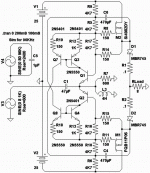
This one I been playing with seems glitch free and has very
good recovery. Which to me more important than extreme
low distortion. Especially in an amp with as much as .25ohm
in series with a live loudspeaker. How flat is any real load?
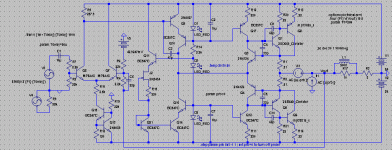
I tried (and for the moment abandoned) diamond buffers.
With my collectors rushed to the opposing bootstrap rails.
I may go back and try diamond again, but these current
mirror style buffers located after the Allison/Aleph comparison
seems to be doing the trick for keeping the input impedance
reasonably high.
I've actually Schaded back the voltage gains of both Aleph
comparators to mitigate the tendancy to over-correct when
tasked with something impossible (like saturation or cutoff).
Try with your Allison Sziklai pairs + Aleph bootstraps and see
how close to the rails that combo gets? Alephs here manage
within 1.4V of either extreme before clipping sets in... And
that swing includes the voltage drops lost to the optional
Schottky shims I have abused for the AB smoothing effect.
Attachments
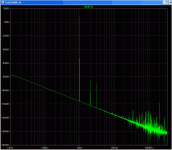
And you asked the THD distortion?
I don't yet know how to make LTSpice calculate...
But here is an FFT of the 1st Watt into 8ohms.
At this low output, the class is still entirely A.
The Quiescent current here is set at 1 Ampre.
Obviously won't stay quite this clean as the power goes up.
I don't yet know how to make LTSpice calculate...
But here is an FFT of the 1st Watt into 8ohms.
At this low output, the class is still entirely A.
The Quiescent current here is set at 1 Ampre.
Obviously won't stay quite this clean as the power goes up.
Attachments
At the 80V 96KHz input you included in the file, the output looks like a half-sine, half-triangle. I am not sure what you mean about recovery, but I assume you mean how well it ignores clipping.
It is somewhat apparent that many of you are light years ahead of me. Oh, well. I am currently trying to get a prototype built with the MJL's and the 2Sx's as output/drivers, and 500mA bias current since that's loud enough and I only have two 12V batteries to run it off of.
Kenpeter, I am not so worried about clipping because it's never gonna happen in my house. Also, I would rather use current/voltage limiting in another part of the amplifier rather than increasing the distortion in the output stage in order to include that feature. That is my preference, though there is a time and place for everything.
Simulated, the distortion was about .009% at 8V output, I believe. In this case, the Allison wins (distortionwise) because it has lower distortion at nearly clipping point. Your graph shows no higher order harmonics, however. There seems to be a trade off between low distortion and low higher-order harmonics.
I have attached my modification of your.asc file, to include a .four statement to measure distortion. I used the [.options plotwinsize=0] line to turn off compression so that the fourier analysis AND your simulation data would be accurate (this is vital for precision work and it doesn't slow things down). If you need things explained in further detail, Email me. In order to view the fourier analysis results, go to the Error Log (View->Error Log).
The input impedance 0f the Allison is very, very low, which is one of the reasons why it has low distortion. So it shouldn't have problems with reactive loads (I'm sure I'm right about this) unless you drive it farther than it's meant to go.
I am not trying to discourage you, I like your input and don't mind it at all as long as it doesn't derail the thread. I am very interested in your ideas about using the Allison as class AB.
Soldering so far has been unimaginably inneficient. Oh well. I will get better.
- keantoken
Attachments
96KHz dummy circuit tricks LTSpice to take a few less math shortcuts.
Never anticipated anyone would attempt to drive the input with it?!?
Doesn't surprise the results of such experiment might be weird...
Perhaps .options plotwinsize=0 what I should have used instead.
Anyways, trying to build an amp that won't ever clip is like trying to
build a dog that won't ever sniff hydrants... It just isn't natural...
You can make voltage rails tall as mountains and limit the input,
you'll still find transient/load interaction it won't like sometimes.
Still, 90% of what we are doing is similar enough... I find ideas in
your designs I would surely borrow. Obsessing upon the lowest
distortion to the exclusion of all else may not make for a practical
amplifier, but everything has its place as art... Keep going with it.
Well, I've given up for the day after trying to point-to-point solder a few things. I can't use a breadboard with those huge output leads. In my anger I decided to try and write an almost-Shakespearean tragedy where an insane engineer kills two innocent coworkers after getting angry about his soldering not working (don't worry, it's just a play  ). I can post it here if there's interest.
Well, this is far more practical than some of my other designs, so I am certainly going to try and get it working. So hopefully it's at least half as material as it is art.
I wasn't intending on building an amp that wouldn't clip. At my listening levels, hopefully it won't do so. But I want it to clip cleanly (without oscillation) whenever it does. According to simulation, I've done that. Too bad it's not so easy to find out in the real world.
- keantoken
I sometimes use many as two irons (one in each hand) and a
heatgun (in a clamp) simultaneously. You can also never have
too much flux. Get you some liquid flux. Be aware you MUST
wash it away immediately afterward, and dry on low heat...
Even if not technically corrosive, the darn stuff does conduct.
If you are trying to do this with a typical pencil iron and no
flux but what comes inside the solder... Results aren't likely
to be pretty. Get in and get out fast. Too little heat over too
long is just as bad as too much.
Make sure to use real tin/lead solder. A little silver is OK too.
Kester always a good brand to look for.
Stay away from lead free (ROHS) stuff, as it melts at higher
temperature and always looks "cold solder joint" even when
done right... Makes inspecting your work more difficult. Less
visual feedback to know when you've done it correctly.
--------------------
Now if you wanted to write a play regarding a bald guy with
tissue rejection issues, and a discount scalp transplant that
constantly has to be replaced by an illegal immigrant surgeon
that he keeps locked in the basement... You could call it "Hell
Toupee"...
Same thing only different...
nice 50 watt amp, keantoken
Thank you. Where have you been? I know my circuits and ideas are getting lame and repetitive but it's still lonely when no one comments on them...
To simplify without reducing performance, I don't think so... But there are a few more small things I know that we can do.
The only thing I think we could simplify without losing performance is the CCS setup, but still I don't know. One thing I can see is that when it gets hot or cold, the LTP can go out of balance. So ideally I would use a two-transistor CCS, so that the temperature coefficient would match that of the VAS most closely and compensate...
Okay then. After changing the LTP CCS, I chose the selection of transistors which caused the least balance shift per temperature in the LTP. This CCS also has better PSRR than the previous one... So it's a win-win. The selection was a 2N5089 to complement the 5087 used in the VAS (It makes sense that two closely related transistors would have close tempcos). Schematic attached...
The LTP balance change per 10 degrees C is 18.7uA, or 174.56uV (taken from emitters and base respectively). This is between the temperatures of 20 and 30 degrees celsius.
There are a number of ways we could try to make it impervious to temperature... Which sounds fun to me. But that will have to wait until a real life prototype is made.
- keantoken
You are right
Simply-fying is not for this.
For givin' out 50 good quality watts this ONE is already simple enough
about temperature behavior
this is often what is a big difference
between a good amplifier designer with lotsa experience
and
the rest of us and the beginners in amp building
guys like John Curl, Bob Cordell, AKSA, Nelson Pass
they know by heart
how to compensate different power transistors in a given
heatsink configuration
the art of temp compensation
is really the test for decide how good you are
----
You still havent commented my firsst post after returninig
http://www.diyaudio.com/forums/showthread.php?s=&postid=1829928#post1829928
 Actually keantoken,
if it wasnt for readning your post in My Audio Forum,
I would nt be here today ....
 http://lineupaudio.freehostia.com/forum/index.php?topic=123.msg809#msg809
My aching heart can not take that Anyone that anyone is ignored
.. I have been ignored so many times myself ...
Your ideas are good & some of them are new.
You really deserve better and our kind attention.
You may very well be our future John Curl .. say in 30-40 yesrs, man!
When many of us are now longer around
halojoy can not brag to be practically best in temp comp
... but theioretically he knows a few good things with vBE multiplying
Simply-fying is not for this.
For givin' out 50 good quality watts this ONE is already simple enough
about temperature behavior
this is often what is a big difference
between a good amplifier designer with lotsa experience
and
the rest of us and the beginners in amp building
guys like John Curl, Bob Cordell, AKSA, Nelson Pass
they know by heart
how to compensate different power transistors in a given
heatsink configuration
the art of temp compensation
is really the test for decide how good you are
----
You still havent commented my firsst post after returninig
http://www.diyaudio.com/forums/showthread.php?s=&postid=1829928#post1829928
if it wasnt for readning your post in My Audio Forum,
I would nt be here today ....
My aching heart can not take that Anyone that anyone is ignored
.. I have been ignored so many times myself ...
Your ideas are good & some of them are new.
You really deserve better and our kind attention.
You may very well be our future John Curl .. say in 30-40 yesrs, man!
When many of us are now longer around
halojoy
... but theioretically he knows a few good things with vBE multiplying
Actually, it's 25W, not 50. I misread the simulator. But I am still pleased with the circuit.
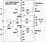
I forgot to post the schematic in my last post, so here it is.
Also lineup, try looking here if you want to see one of my ideas to make it simpler... It will be about as complex as this circuit in real life but it's another idea.
http://www.diyaudio.com/forums/showthread.php?s=&threadid=144034
I feel the same way as you about ignoring and being ignored. I like to think that I know what the person on the other end of the LAN cord feels... And try to act accordingly. I know that whether you are ignored acknowledged can make a large difference in what you do after, since I have been through the process myself quite a few times.
- keantoken
Attachments
keantoken said:Actually, it's 25W, not 50. I misread the simulator. But I am still pleased with the circuit.
You should be able to swing 35WRMS clean sinewave into 8 ohms
with those +25/-25 rails. 70 watts at full clipping. Assuming you
are willing to bootstrap a few of your drive signals and/or bounce
a few off the rail with current mirrors...
Almost ideal power for an Eminence Wizard as the loudspeaker,
but thats mostly characterized for musical instrument amplifier.
Which was what I was aiming to do with mine....
Anyways: 1W RMS output into 8 ohms, is a sine wave of +4/-4
Volts Peak to Peak, or 2.83 VRMS. I think I may have miscalc'd
the 1W swing as +8/-8 Volts in one of my earlier examples???
So the distortion figure as given, may have been for 4W RMS?
have you assumed a bridged pair of amplifiers?kenpeter said:You should be able to swing 35WRMS clean sinewave into 8 ohms
with those +25/-25 rails.
Nope, just bootstraps (instead of CCS) for the drives...
Yes, abusing the amp to pump bootstraps causes some
"distortion"... But for any transients that might attempt
to swing more than 25W clipping, the bootstrapped amp
distorts less...
If the small errors bug you, can add a sidechain to drive
only the bootstraps, still less parts than all that CCS...
This isn't the latest or greatest version of my design.
But an early simple version, that makes easy to see
how straps can be made to swing +35/-35 for driving
purposes and pseudoCCS.
Straps should work equally well with Allison or Aleph...
No special difference in that part of the circuit.
Attachments
Thank you for the bootstrapping idea, Ken. I just simulated it and it gives better performance in this circuit than with the CCS.
I'm sure that if you have high-gain output devices, then the bootstrap current won't affect output linearity enough to matter. If this gives and increase in stability, larger output swing, and better input impedance than I think we have a winner.
In this case, I think the output swing was limited because I was driving the CCS's with LEDs, making their cutoff voltage more.
Now to simulate low frequency and see what happens...
- keantoken
I'm having trouble simulating at low frequency because the caps add a whole lot of LF drift to the FFT and it completely obscures the test frequency's harmonics. This usually isn't a problem as LTSpice does a operating point analysis to put cap voltages closest as possible to their settled state. I keep increasing simulation time but the longer the simulation, the more time it takes to get enough data.
In most cases I can replace the caps with a voltage source but it won't work here because I need to see how the AC characteristic of the caps affect performance.
It seems at the moment that LF distortion has skyrocketed, overshadowing the small decrease in HF distortion.
- keantoken
In most cases I can replace the caps with a voltage source but it won't work here because I need to see how the AC characteristic of the caps affect performance.
It seems at the moment that LF distortion has skyrocketed, overshadowing the small decrease in HF distortion.
- keantoken
- Status
- This old topic is closed. If you want to reopen this topic, contact a moderator using the "Report Post" button.
- Home
- Amplifiers
- Solid State
- 50W, Class A, another one... :)


