Markus,
how is your progress ? have you fix the bugs with the smps ? or you just wait for them to come with a solution. noah, they won't. they will just show-up only when they will want to sell something else, new group bay, collect money again, a ew dozen of mistakes, which of course, are because of chinese cloners, then again silence for half year. they will just simply say: We were in holiday all this time, it was summer, remember ?
how is your progress ? have you fix the bugs with the smps ? or you just wait for them to come with a solution. noah, they won't. they will just show-up only when they will want to sell something else, new group bay, collect money again, a ew dozen of mistakes, which of course, are because of chinese cloners, then again silence for half year. they will just simply say: We were in holiday all this time, it was summer, remember ?
Christi,
Thanks for asking. Yes, there is some progress but not that much as I would expect.
I've got the output inductor but replacing the old inductor didn't change much regarding the output noise. Another issue is that the inductor is slightly too small. It should be most probably 34 mm but due to lack of space on the board my inductor has 27 mm diameter. I assume that it will limit the output current but that's fine for me. I need only 500W output power.
I didn't change the feedback loop according to your schematic because this would require redesign of the printed board. I only added 47n capacitor between cathode and the reference pins of TL431. This improved stability of the feedback loop (and decresed slightly the noise on the output). I know that the compensation should be calculated and not guessed - I will do it in the nearest future.
The biggest gain is with snubbers. But here I found out that calculating the correct parts requires that I know the ringing frequency and the leakage inductance of the power transformer. It seems that the ringing frequency is about 10 MHz (assuming my poor oscilloscope shows it correctly). At the moment I'm looking for a simple inductance meter to measure the transformer. Anyway, changing the snubbers helps a lot.
Another question: on the secondary side shouldn't the snubbers be in paralel with the diodes - I've seen such schematics?
BTW, I have seen this schematic (almost exactly the same) published in another thread on this forum and it was dated 2007.
Mark
Thanks for asking. Yes, there is some progress but not that much as I would expect.
I've got the output inductor but replacing the old inductor didn't change much regarding the output noise. Another issue is that the inductor is slightly too small. It should be most probably 34 mm but due to lack of space on the board my inductor has 27 mm diameter. I assume that it will limit the output current but that's fine for me. I need only 500W output power.
I didn't change the feedback loop according to your schematic because this would require redesign of the printed board. I only added 47n capacitor between cathode and the reference pins of TL431. This improved stability of the feedback loop (and decresed slightly the noise on the output). I know that the compensation should be calculated and not guessed - I will do it in the nearest future.
The biggest gain is with snubbers. But here I found out that calculating the correct parts requires that I know the ringing frequency and the leakage inductance of the power transformer. It seems that the ringing frequency is about 10 MHz (assuming my poor oscilloscope shows it correctly). At the moment I'm looking for a simple inductance meter to measure the transformer. Anyway, changing the snubbers helps a lot.
Another question: on the secondary side shouldn't the snubbers be in paralel with the diodes - I've seen such schematics?
BTW, I have seen this schematic (almost exactly the same) published in another thread on this forum and it was dated 2007
.Mark
if you have no space for a bigger inductor try to find a High-flux type core and use this for the output inductor.
add a 2k2 resistor in series with a 22nf cap instead of a single 47n cap on the 431 legs.
i suggested you to connect the snubbers on the transformer windings because is the only resonable place to put them due to the faulty layout. they will perform almost as they are connected in parallel with the diodes.
the self resonance of the transformer happens at a frequency much higher than the working freq. usually in MHz-10's MHz range, due to the parasitics of the transformer
really ? where ? the schematic posted by them wasn't the original ???
add a 2k2 resistor in series with a 22nf cap instead of a single 47n cap on the 431 legs.
i suggested you to connect the snubbers on the transformer windings because is the only resonable place to put them due to the faulty layout. they will perform almost as they are connected in parallel with the diodes.
the self resonance of the transformer happens at a frequency much higher than the working freq. usually in MHz-10's MHz range, due to the parasitics of the transformer
Christi,
BTW, I have seen this schematic (almost exactly the same) published in another thread on this forum and it was dated 2007
Mark
really ? where ? the schematic posted by them wasn't the original ???
this will happen on regulated supply, only unregulated will stay about the sameI started this SMPS, It works but I have the same problem as Markus:
when I connect unsymmetric load , I get unsymmetric voltages on the output.
Markus did you manage to solve this problem?
Regards
make the changes according to this http://www.diyaudio.com/forums/power-supplies/149702-50v-smps-quasar-amps-others-6.html#post2251576 and will work.
make the changes according to this http://www.diyaudio.com/forums/power-supplies/149702-50v-smps-quasar-amps-others-6.html#post2251576 and will work.
-Salut dl.Cristi.Incerc sa termin sursa aceasta si v-as ruga sa puneti pe thread modificarile de mai sus si in romana.-nu le am cu engleza
-Torul de iesire se poate bobina separat cu 42+42spire ? In acest caz sarma nu intra pe un singur strat si ar trebui sa bobinam pe 2 straturi.
multumesc
Hello dl.Cristi.Incerc source to finish it and I would ask you to put on the thread above changes and I do not have to romana.-English
-Tor output is 42 to 42 separate coil wound? In this case the wire does not fall on a single layer and should coil the two layers.
multumesc
English please
dave

-Salut dl.Cristi.Incerc sa termin sursa aceasta si v-as ruga sa puneti pe thread modificarile de mai sus si in romana.-nu le am cu engleza
-Torul de iesire se poate bobina separat cu 42+42spire ? In acest caz sarma nu intra pe un singur strat si ar trebui sa bobinam pe 2 straturi.
multumesc
if is allowed i will translate what he wrote:
Hi Cristi, i try to finish the smps and i would ask you to write the modifications in romanian language as well (there are some users on a romanian forum which need desperate help and they were abandoned by those who started the project and some of them cannot understand english well)
- The output toroid can be winded separately with 42+42 turns ? in this case the wire cannot fit on a single layer and we would have to wind on two layers.
thank you.
Answer:
numarul de spire se calculeaza in functie de inductanta necesara dupa formula L=Al*ts^2 unde L este inductanta bobinei in uH, ts numarul de spire, Al permeabilitatea miezului.
the number of turns should be calculated with the following formula: L=Al*ts^2 where L is the inductance value in uH, ts, number of turns, Al is the core permeability.
recomand o valoare a inductantei de 40-70uH pentru fiecare infasurare, valoarea nu este critica, dar o valoare mai mica va creste curentul de varf prin tranzistorii din primar va cere un curent de sarcina mai mare pentru ca sursa sa functioneze in mod continuu, iar o valoare prea mare va satura miezul la curenti mari si tranzistorii din primar vor lucra cu curenti de varf mult prea mari.
i recommend an inductance value of 40-70 uH for each winding, the value is not critical, but too low will increase the peak current through the primary mos-fet's and the smps will work in discontinuous mode, and a larger value could saturate the core when the output current is higher.
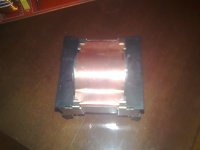
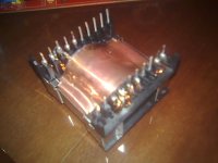
miezul recomandat e un tor de 30-36 mm diametru exterior, culoare verde deschis cu fasie albastra pe o parte, bobinat cu 2 conductoare de 1.2mm diametru, 42 spire. una din infasurari va avea capetele inversate intrarea cu iesirea !!! nu recomand miezurile ieftine galbene cu alb, au pierderi mari si se incalzesc. la frecventa la care se lucreaza si amplitudinea tensiunii varf-la-varf nu e o problema capacitatea parazita dintre spire, deci se poate bobina in mai multe straturi, oricum exista capacitate parazita intre cele doua fire prin care circula curenti de polaritati diferite din moment ce sunt bobinate in paralel. e nevoie de snubbere calculate sa amortizeze oscilatiile care pot distruge diodele.
for the output inductor use a 30-36 mm outer diameter powder core green-blue strip winded with 2 wires of 1.2 mm diameter in parallel, 42 turns. one winding must be 180* out of phase. i don't recommend the yellow white cores, they have high losses and become hot. at this working frequency and pk-pk voltage swing there is not an issue to wind the core with multiple strands, anyway there are two parallel wires which carries opposite currents with significant capacitive coupling. snubbers are highly recommended, sized to damp the oscillations which can kill the rectifier diodes due to overshoots.
I started this SMPS, It works but I have the same problem as Markus:
when I connect unsymmetric load , I get unsymmetric voltages on the output.
Markus did you manage to solve this problem?
Regards
ovidiu1,
One of the output coils must have output/input reversed - see silicipi response in this thread Forumul electronistilor • Vezi subiect - Sursa (SMPS) +/-50v pt amplif
Regards,
Tibi
Hi to All
Yes , Alex mm is very nice one...
I can't find schematic in this topic , Everybody have schematic for
Quasar Smps ?
Regards
Cristi,
can you translate the following into romanian?
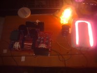
6. chage R8 IMEDIATELY BEFORE THE C26, P1 AND TR4 WILL CATCH FIRE !!!! THIS IS A SERIOUS PROBLEM!!!! PLACE IN PARALLEL WITH C26 A RESISTOR WHICH WILL SET THE MAXIMUM CURRENT FOR EXAMPLE 47R not bigger value than 100R.
7. add a 4k7 resistor in series with the pot. and change the pot to 1k otherwise you have very narrow overcurrent limit.
thank you.
can you translate the following into romanian?
6. chage R8 IMEDIATELY BEFORE THE C26, P1 AND TR4 WILL CATCH FIRE !!!! THIS IS A SERIOUS PROBLEM!!!! PLACE IN PARALLEL WITH C26 A RESISTOR WHICH WILL SET THE MAXIMUM CURRENT FOR EXAMPLE 47R not bigger value than 100R.
7. add a 4k7 resistor in series with the pot. and change the pot to 1k otherwise you have very narrow overcurrent limit.
thank you.
Cristi,
can you translate the following into romanian?
6. chage R8 IMEDIATELY BEFORE THE C26, P1 AND TR4 WILL CATCH FIRE !!!! THIS IS A SERIOUS PROBLEM!!!! PLACE IN PARALLEL WITH C26 A RESISTOR WHICH WILL SET THE MAXIMUM CURRENT FOR EXAMPLE 47R not bigger value than 100R.
7. add a 4k7 resistor in series with the pot. and change the pot to 1k otherwise you have very narrow overcurrent limit.
thank you.
Translation:
6. schimba imediat R8 inainte ca C26 si TR4 sa ia foc !!! asta e o problema serioasa. conecteaza in paralel cu C26 o rez. care va determina valoarea maxima a curentului, de ex. 47R dar nu mai mare de 100R.
a current transformer should NEVER be left with the secondary open or unloaded, or with a load which is too low and will lead to secondary voltage build-up to dangerous values where arching and risk of fire is present for the transformer and other components connected in the secondary side of the CT. this could be also a reason for CT overheating.
--- un transformator de curent nu se lasa NICIODATA cu secundarul in aer sau cu o sarcina prea mica asfel incat tensiunea la bornele secundare sa nu ajunga la valori periculoase, riscand sa ia foc transformatorul sau restul componentelor, precum rezistori si condensatori conectati in secundarul tr. de curent. un alt efect nedorit este incalzirea excesiva a transformatorului de curent. ---
7. conecteaza o rez. de 4k7 in serie cu potentiometrul si schimba valoarea pot. la 1k altfel plaja de reglaj al curentului e prea mica.
Last edited:
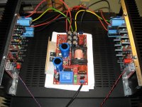
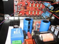
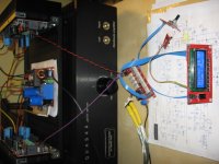
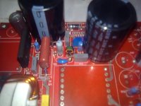
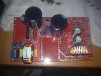
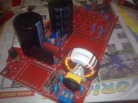
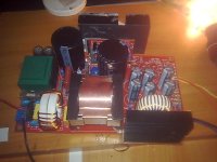
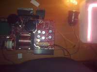
Good morning to all of you, scz my poor english. I made this source after i have red all the information from the romanian forum, and it worked from the first time, if i can i will post some pictures
Attachments
Hello all! I am new at this forum. So... I'm searching for a good SMPS circuit. I would like to use with TAS5630. It needs +-12V and +50V Which is the best solution?
If you are looking for a robust and reliable cct, use SG3525 + IR2110 combo.
If you are looking for modern, soft switching, resonant controller (up to 500W) L6599A is one of the best.
Tibi
- Status
- This old topic is closed. If you want to reopen this topic, contact a moderator using the "Report Post" button.
- Home
- Amplifiers
- Power Supplies
- ±50V SMPS for Quasar Amps (& others)