Book and LLC SMPS
Browns book as well Pressman and Christophe Basso's when used together are powerful tools in power supply design, one drawback is the editing of the manuscripts are sometimes done by students who induce errors ,mostly in the math or values for a plate(schematic) which shows up in the print.
Since you mentioned interest in LLC converters you should visit Fairchilds website and find "Design Considerations for an LLC Resonant Converter" by HangseokChoi "Power Conversion Team". I have researched this with Onsemi and simulated a couple of designs since there is a lot of IC's aimed to aide in design of this type of converter but in mho there are too many disadvantages, the major one is range of operation leading to a pfc front end and that almost rules out high current,high voltage operation since the design of a pfc over 500watts is not a trivial matter.
I think you will find the best frequency of operation lies between 80 to 120kHz and the bobbin for the transformer will more than likely have to be produced by hand(dividers placed on a standard horz ETD bobbin.
Last edited:
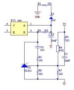
These are not stupid questions. I would ask exactly the same. The way TL431 is used in this SMPS is one of the problems with this SMPS. First of all, the feedback circuit tracks a difference between positive and negative rails (> 100V). And it has no reference to the ground. As a result, when you connect unsymmetric load (e.g. 7+8 Ohms like I did), you get unsymmetric voltages on the output, which may be very dangerous if one of the voltages exceeds maximum voltage for output capacitors. I asked about it on another forum and the answer is that only one rail should be tracked. The other rail voltage will be maintained automatically due to the way the transformer is wound. Theoretically you could track two rails but it has to be done differently (like in A-and-T SMPS). Also the way in which TL431 is used is not correct. You have to take care of not exceeding maximum voltage of the IC (35V) but you also have to provide at least 1 mA current through the IC - otherwise it does not work. To achieve this, you have to change slightly the schematic (I'm working on it at the moment). Also the Zener diodes are not needed. I shorted one of them but I think that the other one is also not needed. The IC is protected against too high voltage by the resistor in series with opto. Also the compensation of the feedback loop has to be taken into account. So there is some work to be done with this IC.(Please stop me if I'm saying stupid things)
Why use that TL431-as-a-ccs-trick in series with the opto and the bunch of zenners which control the actual output voltage?
Why not use TL431 as what it is - a shunt regulator - with ref taken from a vout voltage divider and a-k series with opto led and resistor (as the other smps's use it)? And control the output voltage from the voltage divider (multi-turn pot if you want fine adjusting).
Mark
I think that the last few pages identified all the problems with this SMPS. They are not that serious but they need to be solved before the SMPS is used in an amp. We are very close to have a nice 800W SMPS but it is still ahead of us.
So the problems are:
1. Incorrect way in which the TL431 is used. Hitachi datasheet: http://documentation.renesas.com/eng/products/linear/rej03d0678_ha17431.pdf gives some details on this.
2. Any common-mode choke cannot be used on the output. It seems that details of this choke were never provided (correctly). I mean: material, windings, the order in which windings are connected.
3. Output power. I got 600W out of it (but this is only due to the fact that I have such resistors). It's most probably around 800W. The photos from DJLove are not reliable - he measures the current (10A) without measuring the voltage, or the voltage without measuring the current. He also uses 2x100W resistors. I used 4x100W resistors mounted on a huge heatsink and they really get hot. It means the DJLove did not do any realiable tests on the SMPS.
I think that the switching frequency of the SMPS is around 50kHz and with this frequency and the core used you cannot get 1200W as someone has written.
So it would be nice if someone could correct the first two problems and measure actual power of the SMPS. It also needs to be mentioned that there were some problems with the error amplifier and I'm still not sure whether the change in the feedback loop is correct.
Mark
I think that the last few pages identified all the problems with this SMPS. They are not that serious but they need to be solved before the SMPS is used in an amp. We are very close to have a nice 800W SMPS but it is still ahead of us.
Mark
there are few more problems than those which you mentioned till now.
since the "rats already abandoned the sinking ship" and seems that there is no chance to get help from them anymore (either because they don't care or simply don't know) i will provide you some help to make this ..... work.
take the schematic which was posted before and make the following changes:
first of all, i consider that the pcb is made according to the schematic, if so, change the following:
1. secondary snubber: R15, C37. it has wrong values and it is useless because is placed after the output inductors. use instead 2 snubbers with capacitor value of 470pF and resistor 22R at >3W in parallel with each secondary winding.
2. for the output inductor use a 30-36 mm outer diameter powder core green-blue strip winded with 2 wires of 1.2 mm diameter in parallel, 42 turns. one winding must be 180* out of phase.
3. use the arrangement from the attached schematic for the error amp. this has also compensation and is working stable.
4. decrease the values for Rj3 and RJ4 to 3.3R otherwise the MOS-FET's might blow-up soon due cross-conduction.
5. change C56 to 22nF and add a 33K resistor in series. the upper resistor with just smd marking should be 56k.
6. chage R8 IMEDIATELY BEFORE THE C26, P1 AND TR4 WILL CATCH FIRE !!!! THIS IS A SERIOUS PROBLEM!!!! PLACE IN PARALLEL WITH C26 A RESISTOR WHICH WILL SET THE MAXIMUM CURRENT FOR EXAMPLE 47R not bigger value than 100R.
7. add a 4k7 resistor in series with the pot. and change the pot to 1k otherwise you have very narrow overcurrent limit.
8. on the pcb, cut all the pins of the IR2110 which are not connected. there are few pins which are not used to provided the necessary clearance for to withstand high voltage. this aspect was completly ignored in the design, can see from the pictures.
9. increase the value of C34 to 0.47uF or the ic will enter in UVP mode in certain situation. can connect in parallel a 10uF cap.
10. decrease the value of C9 to 2.2nF to regain the loop stability. in case of instability, remove this cap. you can hear the transformer buzzing or making annoying noises when the loop is unstable.
please make the changes and tell us the result.
felicitatiunile mele k-ati reusit sa facetzi o sursa mai de kkt decat am sperat si amu iati lasat pa astia cu kuru-n praf
Attachments
Hello,
China has created a SMPS for commercial use, and from that moment all replied without even knowing what you know or duplicated.
Markus dear ... look on the market. clone to clone far use with audio amplifiers.
PWM concept unfortunately does not marry well with a fast modulator current "Amplifier". you can try all those who want, all behave the same way.
I keep seeing different brands but always with the same mistakes.")
not attak me for this but engineers without know now necessary.
output filter (toroide ) have mistake material and wiring.
Unbalanced current regulator (asymetric) = not resolvable.
RFI/EMI very high for audio use.
very high IMD at low frequency introduction on amplifier.
please...solve this in all pwm smps.
I mean that is necessary re-develop with new concept for audio amplifiers.
Or use this....Amplifier sounds.
Regards
China has created a SMPS for commercial use, and from that moment all replied without even knowing what you know or duplicated.
Markus dear ... look on the market. clone to clone far use with audio amplifiers.
PWM concept unfortunately does not marry well with a fast modulator current "Amplifier". you can try all those who want, all behave the same way.
I keep seeing different brands but always with the same mistakes.
not attak me for this but engineers without know now necessary.
output filter (toroide ) have mistake material and wiring.
Unbalanced current regulator (asymetric) = not resolvable.
RFI/EMI very high for audio use.
very high IMD at low frequency introduction on amplifier.
please...solve this in all pwm smps.
I mean that is necessary re-develop with new concept for audio amplifiers.
Or use this....Amplifier sounds.
Regards
Last edited:
Hello,
China has created a SMPS for commercial use, and from that moment all replied without even knowing what you know or duplicated.
i noticed that english is not your best point, but maybe you can explain what you mean in the above sentence
the story behind is simple.
one year ago, the "master" of this project contacted me and ask me if i can make for him 50-100 pcs of "this" smps. he pointed me to the schematic from that forum, i told him from the very beginning that the schematic was wrong, and could not work. i have made my own smps before that and i have used the same ic's. i offered him that one instead. just because he ask me the quotation and no details at all, expecting me to provide the details, i sent him couple of days later a mail with complete schematic, bom, pcb files and quotation for complete assembled and delivered to rromania. the price was below half of the price which they had asked eventually for the parts only, from their project BOM. it was clear for me that they had no intention to buy something from me ever, but to get the schematic, and the price quotation to see what competition can do. then they start blaming, attacking and all kind of garbage against.
as can be seen here, Connexelectronic i have the smps available since more than one year ago. then in september last year they accused me that i have cloned something which till today, one year later doesn't exist or at least i never saw someone to post clear, and detailed informations about.
now, simple question, if mine is CLONE, where is the ORIGINAL working, tested, sold.
Hello..
I have no speech against you.
my speech is oriented in general, what I said refers to a reality in this market.
I do not know that you have the SMPS or the story behind it (I do not know how).
SMPS when I saw this on the thread I tried to give a hand to the transformer.
or I tried to advise Markus for filter output.
Sorry for my English.
My complaint is addressed to all declared SMPS for audio (but not for audio, are for bulbs.
If you have curiosity see an smps specifically created for audio (around digital amplifier) then I can send you photo.
Regards
my explanation regarding your quote was given in the first sentence of the reply. then the story is for those who had maligned both here and there.... about who's first, the chicken or the egg.
i have no doubts that soft-switched smps has better performance for audio than hard switched ones, that's why i'm moving toward this direction with my latest products.
but... there are fields of applications where a smps must exceed the requirements for an audio smps and if that one can be done, where's the problem for audio ?
off topic: Markus, look at the positive aspect: having this troubles with an incomplete and wrong smps project, by now, you already learnt more about smps than those who initially claim that they made-it. keep on and soon you'll be able to make your own from scratch.
my explanation regarding your quote was given in the first sentence of the reply. then the story is for those who had maligned both here and there.... about who's first, the chicken or the egg.
i have no doubts that soft-switched smps has better performance for audio than hard switched ones, that's why i'm moving toward this direction with my latest products.
but... there are fields of applications where a smps must exceed the requirements for an audio smps and if that one can be done, where's the problem for audio ?
off topic: Markus, look at the positive aspect: having this troubles with an incomplete and wrong smps project, by now, you already learnt more about smps than those who initially claim that they made-it. keep on and soon you'll be able to make your own from scratch.
Hi,
I agree that Markus or others have done the right thing and have the opportunity to deploy their knowledge by solving problems. this is good.
Is clear that some other professional fields require special SMPS (I know). and then you can do something good for audio.
but it is not easy to have knowledge about new methods.
I have no doubt that other engineers will PSU really special for audio.
Regards
"............then I can send you photo............."
Can you post it here as it seems to be On Topic !
Thanks.
I think that can do a good information because it is
really new concept and measures AB or Class D amplifier show better behavior of toroidal 50Hz with big capacitors without all noise or RFI/EMI.
DPS-500 for digital amp.
DPS-600 for Mospower A-B amp.
You can see on "audiopower.it"
Because i know very long time for develop and research ,then I not support
SMPS for lamps ..declared for Amplifier.
Christi, you are right. When I started this SMPS, several guys claimed that it is too difficult for me (I had never build such a SMPS). But I build it and it works. It has some problems but I intend to solve them (hopefully with you guysoff topic: Markus, look at the positive aspect: having this troubles with an incomplete and wrong smps project, by now, you already learnt more about smps than those who initially claim that they made-it. keep on and soon you'll be able to make your own from scratch.
). I had to learn a lot about TL431, about feedback loop, transformer winding and stuff like this. I'm very grateful for your help (Christi and AP2). One question Christi; in your schematic of the feedback loop it looks like you are tracking the voltage between V+ and V-, which I tend to consider a mistake. What happens if you put an unsymmetric load on the output? Will the output voltages be still symmetric? I had such a case with an 200W MOSFET amp which had unsymmetric input stage. And as a result, the voltages were unsymmetric. I think that it is enough to track one voltage. The other voltage will rely on transformer winding closely coupled (if this is the correct term). Have you done such test?
Mark
Chas, those two books are on my list (soon). Is it correct that Basso's book is more SPICE oriented? I learn LTSpice and I'd like to use it with this SMPS (for example to check the feedback loop).Browns book as well Pressman and Christophe Basso's when used together are powerful tools in power supply design, one drawback is the editing of the manuscripts are sometimes done by students who induce errors ,mostly in the math or values for a plate(schematic) which shows up in the print.
Also thanks for help with the output inductance.
Mark
Hi Markus,
Montenegro as you are getting? is good for relaxation?
for feedback, this reflects the toroid output is better than the first solve output filter with toroidal iron powder (yellow), others will tell you another color eheheh! This is normal chaos.
Regards
Montenegro as you are getting? is good for relaxation?
for feedback, this reflects the toroid output is better than the first solve output filter with toroidal iron powder (yellow), others will tell you another color eheheh! This is normal chaos.
Regards
Last edited:
I'm back from Montenegro. It's a little bit too far. Next time I'll go to Croatia. I've been in this hotel: Hotel Croatia - Luxury Hotel Croatia - Cavtat - Dubrovnik, Croatia for 1 day. What a place - but it's expensive. I would need to design a very good SMPS and sell it on the market to go there for a longer timeHi Markus,
Montenegro as you are getting? is good for relaxation?
for feedback, this reflects the toroid output is better than the first solve output filter with toroidal iron powder (yellow), others will tell you another color eheheh! This is normal chaos.
Regards
. Montenegro is more for people who like adventures (I was in Ulcinj - a town where pirates stayed there even in the XIX century).I think that the colour of the core does not matter. Important is the material that it is made of. Some manufacturers paint it yellow and the others paint it green. It should be a certain matarial (iron powder) with known parameters that allow performing calculations.
Mark
The core which i suggested for the output inductor is made on the 52 type material or green/blue color. it has similar properties as the popular yellow/white but much lower losses. quote from Micrometals catalog: "-52 Material This material has lower core loss at high frequency and the same permeability as the -26 Material. It is very popular for high frequency choke designs."
At frequencies over 50 KHz i do not recommend to use the -26 material due to the increased core losses.
the feedback which i'm using alows a very tight regulation between both rails, even if one is unloaded and the other is fully loaded. for example, a A1000SMPS with output set at +-60V, if i load one of the outputs with 8A, and the other one, zero load, the output voltage will be about 59.7 on the loaded one and 60.3 on the unloaded one. and the voltage between the + and - rail will be the same, 120V. who have a A1000SMPS can have a try.
the idea is simple. first, the output inductor helps a lot to cross-regulate the outputs, since is winded with equal number of turns, in parallel, and has a very low lk. inductance. just remember that one of the windings must be 180* out of phase. then the error amplifier is biased from GND as well, not only from positive rail.
Markus, have a try and tell us the result.
At frequencies over 50 KHz i do not recommend to use the -26 material due to the increased core losses.
the feedback which i'm using alows a very tight regulation between both rails, even if one is unloaded and the other is fully loaded. for example, a A1000SMPS with output set at +-60V, if i load one of the outputs with 8A, and the other one, zero load, the output voltage will be about 59.7 on the loaded one and 60.3 on the unloaded one. and the voltage between the + and - rail will be the same, 120V. who have a A1000SMPS can have a try
.the idea is simple. first, the output inductor helps a lot to cross-regulate the outputs, since is winded with equal number of turns, in parallel, and has a very low lk. inductance. just remember that one of the windings must be 180* out of phase. then the error amplifier is biased from GND as well, not only from positive rail.
Markus, have a try and tell us the result.
Christi,
I looked at your recommendations - everything makes sense. Can you only explain this change: "10. decrease the value of C9 to 2.2nF to regain the loop stability". Which capacitor did you mean? C9 is a bridge capacitor.
It's not that easy to test all these changes since some of them would require different PC board (e.g. feedback loop). I'm looking for output inductor core.
I did some tests with snubbers on the secondary side of the transformer. The signal does not look good and after adding a snubber directly on the transformer secondary winding it does not change much. Can you take a look at the photos below? You can see that the rising edge of the signal looks bad (but please take into account that the oscilloscope is not of the highest quality). Can this be caused by gate resistors, or is it leakage inductance of the transformer? Most probably adding correct snubbers would require a much better oscilloscope.
The load was 200W.
Mark


I looked at your recommendations - everything makes sense. Can you only explain this change: "10. decrease the value of C9 to 2.2nF to regain the loop stability". Which capacitor did you mean? C9 is a bridge capacitor
.It's not that easy to test all these changes since some of them would require different PC board (e.g. feedback loop). I'm looking for output inductor core.
I did some tests with snubbers on the secondary side of the transformer. The signal does not look good and after adding a snubber directly on the transformer secondary winding it does not change much. Can you take a look at the photos below? You can see that the rising edge of the signal looks bad (but please take into account that the oscilloscope is not of the highest quality). Can this be caused by gate resistors, or is it leakage inductance of the transformer? Most probably adding correct snubbers would require a much better oscilloscope.
The load was 200W.
Mark
Last edited:
Hi Markus,
sorry for delay. Luxuria hotel very nice for relax with..woman
return at smps...(Fortunately your oscilloscope shows in very slow transient mode .. eheh!)
RFI-EMI is up corner of square wave.
very high harmonics (needle in fast oscilloscope will be very large).
I do not have the present scheme with modifications. perhaps I can see some value eg. what is value of snubbers on primary? (RC)
Last edited:
Current schematic is available here: http://www.diyaudio.com/forums/power-supplies/149702-50v-smps-quasar-amps-others-27.html#post2236209
The primary side snubbers is 47R+470pF.
Yes, I know that I need a better oscilloscope. The one that I have is ~20MHz and most probably I need at least 100MHz or even 200MHz.
Mark
The primary side snubbers is 47R+470pF.
Yes, I know that I need a better oscilloscope. The one that I have is ~20MHz and most probably I need at least 100MHz or even 200MHz.
Mark
felicitatiunile mele k-ati reusit sa facetzi o sursa mai de kkt decat am sperat si amu iati lasat pa astia cu kuru-n praf
Bravo Cristi,
Ce sa-i faci ... asa-i romanu. Trebuie sa reinventeze apa calda ca sa o mai vanda o data.
Sorry for the non official language.
Best Regards,
Savu Silviu
- Status
- This old topic is closed. If you want to reopen this topic, contact a moderator using the "Report Post" button.
- Home
- Amplifiers
- Power Supplies
- ±50V SMPS for Quasar Amps (& others)