hi apex sir,
can u upload a bridge switch image.
Attachments
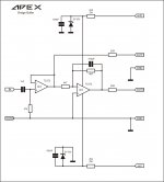
post3027
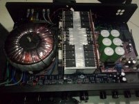
the output stage is bolted to the fins of the heatsinks.
They should be bolted to the core of the heatsink.
The core at the bottom is the wider one intended for device bolting.
The heatsink fins are not in the airstream.
The heatsink should be in a tunnel that constrains the cooling air to flow along bwteen the fins.
The fan is not connected to the heatsink tunnel. The air will take the least resistance path to avoid going through the sink.
Your Thermal design is so badly flawed that your risk severe overheating.
good look
What use are these two comments when they both ignore the obvious implementation errors?Nice work,
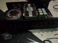
Andrew, look carefully at that heatsink.
Where would you place the output transistors?
And yes since he build a lovely amp, maybe he should put a blanking plate over the current hole for fan, and line the centre fan up with the centre of the heatsink.
Remember the fan must blow thought heatsink tunnel and not suck")
Regards on nice amp.
Where would you place the output transistors?
And yes since he build a lovely amp, maybe he should put a blanking plate over the current hole for fan, and line the centre fan up with the centre of the heatsink.
Remember the fan must blow thought heatsink tunnel and not suck
Regards on nice amp.
Last edited:
The heatsink has a thick core running vertically in the laid on it's back assembly.
That thick core is intended for attachment of the devices to be cooled.
The core is not symmetrical. The region at the bottom is significantly wider than the region at the top.
That is where I would attach all the devices. NOT on the fins.
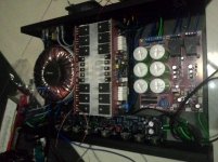
BTW,
I did look carefully. That is how I was able to assess his/her implementation.
That thick core is intended for attachment of the devices to be cooled.
The core is not symmetrical. The region at the bottom is significantly wider than the region at the top.
That is where I would attach all the devices. NOT on the fins.
BTW,
I did look carefully. That is how I was able to assess his/her implementation.
Andrew, look carefully at that heatsink.
Last edited:
can i use 2 ohms speaker in apex b500 tef with 50 0 50v ac transformer??
It's possible, using TEF with more powerful output devices. 2sc4793predriver+2SC5200driver+MJL21193output
Sajti
almost certainly not.It's possible, using TEF with more powerful output devices. 2sc4793predriver+2SC5200driver+MJL21193output
Sajti
It's not only about temperature de-rated SOA. It's about current.
The current demanded by the load must come through the output devices from the drivers and pre-drivers.
almost certainly not.
It's not only about temperature de-rated SOA. It's about current.
The current demanded by the load must come through the output devices from the drivers and pre-drivers.
Will work for sure. Check the Mackie M1400. With 4 pairs of MJL21193/4, running +/-80V, gives about 700W for 2 ohms.
Sajti
70Vpk (from +-80Vdc supplies) into 2r0 resistor test load is equivalent to 35Apk.
When driving a reactive speaker load the current demand on transients can be anywhere from 150% to 500% of the resistive test current.
Expect peak transient currents of 52.5Apk to 175Apk
A 4pair output stage will have to pass upto 20Apk regularly through each output device.
One needs to look at the transistor gain for 20Apk and determine the peak transient base current.
Then work through the stages to determine the pre-driver and VAS peak currents.
Working in ClassG & H does not provide any solution for this peak current demand made by reactive speakers.
- Home
- Amplifiers
- Solid State
- 500W PA amplifier with Limiter