Ah, ok.
I saw in the schematics of Lesha´s DAC, that he connect Pin 16 directly without any C´s. jstang insert 100pf.
Should i do it with or without C´s?
I saw in the schematics of Lesha´s DAC, that he connect Pin 16 directly without any C´s. jstang insert 100pf.
Should i do it with or without C´s?
Looking at Leshas DAC,both oscillators have the 470pF. So they're both running, probably out of sync, but they're tied together, so possibly pulling on each other, conflicting rather than working in sync.
Its probably better to just have one oscillating, but driving the other pin 16s.
Its probably better to just have one oscillating, but driving the other pin 16s.
I/V Resistor quality
Does anybody tried different resistors for passive I/V conversion like Dale RN55, Allen Bradley, Vishay Bulk Metal Z-Foil ect?
I think there were different sound character with the type of resistor.
BTW, here are the chematics of the DAC 1541A 4.0 NOS circuit.
Does anybody tried different resistors for passive I/V conversion like Dale RN55, Allen Bradley, Vishay Bulk Metal Z-Foil ect?
I think there were different sound character with the type of resistor.
BTW, here
are the chematics of the DAC 1541A 4.0 NOS circuit.fastvideo said:Me too with 1541.
I have 2 in parallel.
With pin16 connected together, it sounds like more detail. WHY???
When pin16 was seperated, no big difference compare with single.
With pin16 connected, there is a waveform difference, does it mean it has a more precise dem clock?
philpoole said:Looking at Leshas DAC,both oscillators have the 470pF. So they're both running, probably out of sync, but they're tied together, so possibly pulling on each other, conflicting rather than working in sync.
Its probably better to just have one oscillating, but driving the other pin 16s.
This is where I don't understand.
I try to find an answer for this
What about if I put a dem reclock circuit that I found from EC's thread, did anyone compare this reclock on single and no reclock 2 pin16 connected, which sound better?
philpoole said:That's a good question.
I had never assumed the 100pF necessary, just the 470pF, although there might be a logical reason.
With 4 DACs, who will be the master? You might get a race condition....?
Meaning the synchronization may shift from dac to dac. By using the coupling caps you are nominating a Master for every one else to stay synced to.
I don't know for sure...as I did not try it without the 100Pf, but the sound improvement with the 100Pf sync coupling caps was clearly heard in a few seconds after playing some music it on.
jk
Because one of the 15µF coupling caps on the -15V line just blow up ,
i change all these caps to (4) Black Gate 100µF/16V N-Type.
 Jesus Christ..... Is this a heavenly sound, wonderful.....
I just orderd the same BG´s for the +5V and -5V lines
I´m wondering what happened when i change these caps...
...flying into the orbit...
,i change all these caps to (4) Black Gate 100µF/16V N-Type.
Jesus Christ..... Is this a heavenly sound, wonderful..... I just orderd the same BG´s for the +5V and -5V lines
I´m wondering what happened when i change these caps...
...flying into the orbit...
philpoole said:Hi Jk,
So, do all your DACs have 470pF across pins 16 and 17 as well as connecting them together?
Yes the 470pf from 16 to 17 and the 100pf from pin 16 of the slave DACs to pin 16 of the DAC I picked as the master....
Johnk
Yes the 470pf from 16 to 17 and the 100pf from pin 16 of the slave DACs to pin 16 of the DAC I picked as the master....
Unfortunately you can't slave TDA1541A DEM oscillators this way. When you remove the 470pF caps from the other 3 TDA1541A chips, the DEM oscillators of these chips will oscillate at maximum frequency (around 7 MHz) due to stray capacitance. This frequency will simply inter-modulate with the approx. 250 KHz DEM oscillator from the master.
The following problems have to be solved:
- Preventing the DEM oscillator from oscillating (7 MHz)
- Feeding it with signals that will force the dem oscillator circuit to synchronize.
- Preventing inter-modulation between DEM clock and bit clock.
- Reducing DEM clock jitter.
The TDA1541A sound quality is dominated by the DEM clock, because the DEM clock directly affects bit errors / distortion. DEM stands for Dynamic Element Matching. It's a circuit that dynamically corrects current divider tolerances. The better the DEM clock, the lower the bit errors.
Current dividers can be passive (emitter scaling), or active, using Dynamic Element Matching. The function of a current divider is splitting-up a reference current (say 2mA) into a number of equal currents. Example, 2mA reference current is split-up in 4 x 0.5mA. By dong so, binary weighted currents can be obtained:
2mA, 1mA, 0.5mA, 0.25mA, 0.125mA, 62.5uA, 31.25uA, 15.625uA, 7.8125uA, 3.90625uA, 1.953125uA, 0.9765625uA, 0.48828125uA, 0.244140625uA, 0.122070312uA, 61.035156nA
These are the currents produced by the TDA1541A current dividers. The 6 MSBs have active current dividers (DEM), the 10 LSBs have passive current dividers (emitter scaling).
All 16 derived currents are permanently available. Each output current connects to a diode-transistor bit switch. By using bit switch combinations, 65536 different analogue output currents can be generated.
The DEM clock drives the active dividers that are used for the TDA1541A 6 MSBs. These active dividers consist of a passive divider (with tolerances) and a time averaging circuit that basically averages between 4 not completely equal input currents. Example:
0.496mA, 0.502mA, 0.499mA, 0.506mA. Total equals 0.496 + 0.502 + 0.499 + 0.506 = 2.003mA, after time averaging using exactly the same time intervals between each input selection, all output currents equal 2.003 / 4 = 0.50075mA. These time intervals are created by the DEM oscillator, so when the DEM clock isn't perfect (jitter / drift), the active dividers will introduce errors that lead to bit errors and audible distortion.
The active divider output signals contain switching noise and ripple voltage caused by tolerances in input currents (prior to averaging). That's why a filter is required for each active divider. The filter contains of an integrated resistor and an external 100nF capacitor. These capacitors have to filter RF frequencies (200 KHz and up), so connections must be kept very short (few mm), and the film capacitors must have low inductance (small SMD film caps).
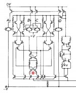
I attached the TDA1541A internal schematics of the DEM oscillator circuit, the 470pF external capacitor is marked red. By studying this schematic, you will notice that a single 100pF cap won't be able to synchronize this type of oscillator. The -V in the schematic represents -15V.
The best way of synchronizing the DEM clock is injecting a differential external clock signal into pins 16 and 17. So one non-inverted and one inverted clock. The frequency must be a multiple of FS (usually 44.1 KHz) and must run in sync with BCK. Practical external DEM clock frequency could be 352.8 KHz (BCK divided by 8).
My latest circuit uses a 74HC00 with pin7 (GND) connected to -15V of the DAC, and pin 14 (VCC) connected to -5V through a 5V1 zener and 220 Ohm resistor. Decoupling cap (100nF) connected between pin 7 and 14.
The chip now runs on approx. 4.9V power supply, but "GND" now equals -15V, and the output signal swings between -15V and -11.9V. This level is ideal to synchronize the DEM oscillator and prevent it form oscillating at 7 MHz.
The outputs of the inverter directly drive the pins 16 and 17 through 2K2 resistors (no capacitors). I use 2 gates of the 74HC00 to create a differential signal: pin 1 & 2 tied together (input) pin 3, 4, and 5 connected together (inverting output), pin 6 is the non-inverting output. Pin 16 connects to pin 3,4,5, through the 2K2 series resistor and pin 17 connects to pin 6 through the 2K2 series resistor.
I feed the input using a 15V zener diode and a 2K2 series resistor, these act as level translator. Drive circuit is connected to GND and produces 5V TTL.
Separate circuit is used for each TDA1541A, all circuits are fed from one 352.8 KHz clock (BCK divided by 8, using a 74HC4040 for example). This way all TDA1541A chip DEM oscillators can be clocked synchronously.
Attachments
EC,
How to explain with 470pf between pin16, pin17 and connecting only pin16 together of each TDAs, I found the sound is better? Is this something to do with the DEM clock, how?
Can you post a link to your latest DEM clock or schematic circuit in this thread here, please?
Thank you.
How to explain with 470pf between pin16, pin17 and connecting only pin16 together of each TDAs, I found the sound is better? Is this something to do with the DEM clock, how?
Can you post a link to your latest DEM clock or schematic circuit in this thread here, please?
Thank you.
Hi John,
If all DAC chips still have the 470pF connected between pins 16 and 17, The DEM oscillators will oscillate at a frequencies between approx. 150 and 300 KHz, but they don't run in sync. By connecting pin 16 of all DAC chips, there will be unpredictable interaction between the 4 DEM oscillators, in some cases this may lead to better perceived sound quality. But it's not optimal and usually not stable (performance keeps varying).
I attached a photograph to illustrate what's wrong when only using the 470pF external capacitor. The upper picture illustrates how the DEM clock looks like when the chip is processing data (pin 17). The DEM clock looks a bit better when the DAC chip receives no data. The oscillogram shows severe jitter (frequency fluctuations) that will lead to bit errors as the time averaging is no longer accurate.
The lower picture shows what happens when the DEM oscillator is forced to run synchronous with an external low jitter clock signal that in turn runs in sync with BCK. Now the DEM clock is locked to a low jitter crystal clock, timing is much more accurate and bit errors are reduced.
The upper trace shows the BCK signal (2.8224 MHz), the lower trace shows the synchronized DEM clock.
I will take a screen shot of the basic schematics and post it.
How to explain with 470pf between pin16, pin17 and connecting only pin16 together of each TDAs, I found the sound is better? Is this something to do with the DEM clock, how?
If all DAC chips still have the 470pF connected between pins 16 and 17, The DEM oscillators will oscillate at a frequencies between approx. 150 and 300 KHz, but they don't run in sync. By connecting pin 16 of all DAC chips, there will be unpredictable interaction between the 4 DEM oscillators, in some cases this may lead to better perceived sound quality. But it's not optimal and usually not stable (performance keeps varying).
I attached a photograph to illustrate what's wrong when only using the 470pF external capacitor. The upper picture illustrates how the DEM clock looks like when the chip is processing data (pin 17). The DEM clock looks a bit better when the DAC chip receives no data. The oscillogram shows severe jitter (frequency fluctuations) that will lead to bit errors as the time averaging is no longer accurate.
The lower picture shows what happens when the DEM oscillator is forced to run synchronous with an external low jitter clock signal that in turn runs in sync with BCK. Now the DEM clock is locked to a low jitter crystal clock, timing is much more accurate and bit errors are reduced.
The upper trace shows the BCK signal (2.8224 MHz), the lower trace shows the synchronized DEM clock.
Can you post a link to your latest DEM clock or schematic circuit in this thread here, please?
I will take a screen shot of the basic schematics and post it.
Attachments

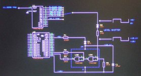
Well, here is the screen shot,
The other 3 TDA1541A chips can be connected to pin 6 of U3B and pin 3 of U3A, using 6 extra 2K2 resistors (R2 / R3). One could experiment with the 5V power supply for U3, the voltage across U3 power supply pins (7 and 14) must be around 5V.
The circuit receives the DEM clock from a divider (U1), different DEM frequencies can be tested for best audible results. The clock divider is driven by a 11.2896 MHz master clock or the MCK output from a CS8412/CS8414/CS8416 (pin19) or the system clock output PCM2706/7 (FUNC2, pin18).
U3 (74HC00) provides the differential DEM signals and correct DC offset (clock signals are referenced to -15V). These signals are fed into inputs 16 and 17, forcing the on-chip DEM oscillator circuit to follow the external differential clock signal. The DEM oscillator won't oscillate due to the external drive signal properties.
Attachments
-ecdesigns- said:Well, here is the screen shot,
The other 3 TDA1541A chips can be connected to pin 6 of U3B and pin 3 of U3A, using 6 extra 2K2 resistors (R2 / R3). One could experiment with the 5V power supply for U3, the voltage across U3 power supply pins (7 and 14) must be around 5V.
The circuit receives the DEM clock from a divider (U1), different DEM frequencies can be tested for best audible results. The clock divider is driven by a 11.2896 MHz master clock or the MCK output from a CS8412/CS8414/CS8416 (pin19) or the system clock output PCM2706/7 (FUNC2, pin18).
U3 (74HC00) provides the differential DEM signals and correct DC offset (clock signals are referenced to -15V). These signals are fed into inputs 16 and 17, forcing the on-chip DEM oscillator circuit to follow the external differential clock signal. The DEM oscillator won't oscillate due to the external drive signal properties.
I think that´s something interresting to bring it on a PCB! Perhaps with a Clock from Guido Tent.
Hi EcDesigns,
Thanks for the excellent description. I've not had any luck with DEM reclocking. I tried it a long time ago, but it just seemed to perform as if no Cosc was fitted. I can't recall the circuit I used, and perhaps it wasn't referenced to -15V so maybe I shall have another go one day.
Cheers,
Phil
Thanks for the excellent description. I've not had any luck with DEM reclocking. I tried it a long time ago, but it just seemed to perform as if no Cosc was fitted. I can't recall the circuit I used, and perhaps it wasn't referenced to -15V so maybe I shall have another go one day.
Cheers,
Phil
Markuzz said:Hi DVB projekt,
Any news on the sound improvement by installing the BG´s on the +5V and -5V lines?
Yes!!!
Therefore i must lift the 4.0 Module, because the BG´s are to high for the standard connection pins. I informed Hui Man Ying about this fact, and i hope he will change the pins for higher ones.


With the BG´s on the three power lines, the DAC jumped to the "next level"
This changes the sq much more than the upgrade of the 0,47µF NX-HQ decouling caps.
But both together..... it is realy beautyful

The next upgrade step is the cap-rolling to claritycap MR in the output stage!

Perhaps i took a look also on the PSU-Caps. We will see.....
Best regards
- Home
- Source & Line
- Digital Line Level
- 4xtda1541a Nos Dac Project