It's right, the source follower has enough low output impedance.@euro21 - I'm shamelessly following the path others have trod in front of me:
https://www.bartola.co.uk/valves/2020/12/29/01a-low-gain-dht-preamp/
4P1L
Attachments
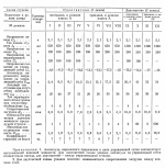
A little about 4P1L http://www.klausmobile.narod.ru/testerfiles/4p1l.htm
Quick translation of words can be done using https://quest-app.appspot.com/download
Quick translation of words can be done using https://quest-app.appspot.com/download
Attachments
Yes - R1 carries all the current, so you can measure the voltage across R1 and use ohm's law to find the current.Rod - is there a handy way (other than a series resistor) to measure filament current with the regulator? I know I could add in a 1r resistor, but if there is a way already, then great!
Thanks Rod. Set now at 550mA.
I did another few changes - I swapped out my CRCRC HV supply for a Maida reg and a little more tidying up on the wiring. Also, I swapped out the EI transformers I had for the filament supplies for an R-core - this was a tad quieter so kept it in.
Having said that, the addition of the Maida reg, combined with a voltage divider on the output has made a huge difference. I believe the power supply has cleaned up the sound a bit, and the voltage divider dropping the gain a bit means all those mad microphonics are gone now, and I have a really clean sound with big soundstage. It still doesn't have the midrange bloom of the 01a, but thats fine, and that comment shouldn't be taken as any sort of criticism. The pre sounds cleaner than the 01a tbh. And this is with a simple divider at the output, and ideally I would need to add the source follower to complete the circuit. I found before on other builds the source follower makes a bigger difference on the low current valves (01a) compared to higher current valves (say 3a5 with sections in parallel).
So I will listen now for a while and assess to see how it goes.
I've had this on a soak test all day. At one point I began to get a little paranoid that the output caps I had (2x 0.1uf FT3) might have been a bit small, so I swapped in a 1uF k75. Other than that little change (which might be meaningless) the pre has been rock solid all day. Running at 15mA per valve using screen mode, 550mA for the filaments. Voltage divider on the output. Gain is ~5x (after implementing the attenuator), square wave is clean as a whistle up to 20khz, and output is a straight line up to 20khz as well. I have to put my ear to the speaker to hear anything.
Subjectively, the sound is excellent. It is a cleaner sound than the 01a, but its not cold or lacking in anything either. It is very dynamic and crisp, in short I'm really happy with it.
Can I ask you gurus about the voltage divider on the output. My limited understanding is that this could form a filter if eg the interconnects had high capacitance, or if the power amp was low input impedance. What is a good way to size the resistance of the divider? For example Ale uses a divider 100k-29k, but why thee values - why not 50k-15k, or 200k-50k? I know Ale has the source follower after his divider, which I gather has high input impedance and low output impedance so is very easy to drive.
Why not 26, not enough?I think if I keep it as is, then I will probably use a pair of Ale Moglias source followers to solve that issue...
But before I do that I want to try the 2P29L and see which I prefer.
Oh sorry!! No particular reason - the 2P29L has the same socket, and very similar heater etc so it will almost drop in for the 4P1L (some socket connections to change) keeping filament bias etc.
This started because I had a ready made chassis, I had 4P1L valves, a set of Ale's boards and the parts. I saw the 2P29L mentioned everywhere in similar setups to 4P1L hence I went for it.
This started because I had a ready made chassis, I had 4P1L valves, a set of Ale's boards and the parts. I saw the 2P29L mentioned everywhere in similar setups to 4P1L hence I went for it.
Thanks @merlin el mago - there certainly seems to be a magic with these DHT valves in preamps.
I can only imagine how difficult this was before Rod and Ale produced their boards for these valves. It certainly has made it possible for someone like me to make and run these fantastic sounding valves. I know there are other heater supplies as well of course, but someone needs to assign bodyguards to these fellas to make sure nothing happens them. 
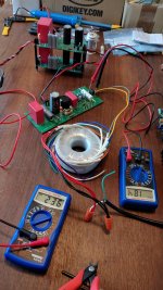
I've started back in on this project after some time away. Recently I finished the final assembly of Ale's HT power supply board. I got about 255V out which feeds into his cap multiplier board set to 235V out as seen in pic.
Yesterday I fired up my gyrator boards for the first time. They came preassembled and I able to set the output on the anode takeoff at 155V to start.
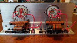
I've attached a pic of my tube termination board. Here on the bottom you can see a string of 6 SIC diodes along with a 3.6ohm resistor to get the last little bit of voltage drop.
I was curious to hear from those who have done filament bias using this hybrid approach. I understand a bit about resistance in the cathode being reflected back through the tube. My question concerns the order of the components.
When I read about people saying to use a high quality Russian wire wound that is in the context of just the resistor. Does it make sense to think that having the diodes as the first elements will "isolate" the potential sound impact of the resistor? Would there be any change in placing the resistor in line first?
You can see on the right hand side I takeoff from pin 8 to the anode of the first diode. I pick up the resistor at the other end and then have the ground point ready back at the other end of it.
I expect my bias voltage with diodes and resistor to be a bit above 8V running 590-600mA through the filament. If I understand right my bias value will be fixed and I will the adjust the gyrator voltage to ultimately set current.
Whats the current suggestions for this tube based on peoples recent experience? Should I expect better performance if I get current up to mid 30's? Do I go lower on filament bias at 550mA or go and push it towards 650mA?
Yesterday I fired up my gyrator boards for the first time. They came preassembled and I able to set the output on the anode takeoff at 155V to start.
I've attached a pic of my tube termination board. Here on the bottom you can see a string of 6 SIC diodes along with a 3.6ohm resistor to get the last little bit of voltage drop.
I was curious to hear from those who have done filament bias using this hybrid approach. I understand a bit about resistance in the cathode being reflected back through the tube. My question concerns the order of the components.
When I read about people saying to use a high quality Russian wire wound that is in the context of just the resistor. Does it make sense to think that having the diodes as the first elements will "isolate" the potential sound impact of the resistor? Would there be any change in placing the resistor in line first?
You can see on the right hand side I takeoff from pin 8 to the anode of the first diode. I pick up the resistor at the other end and then have the ground point ready back at the other end of it.
I expect my bias voltage with diodes and resistor to be a bit above 8V running 590-600mA through the filament. If I understand right my bias value will be fixed and I will the adjust the gyrator voltage to ultimately set current.
Whats the current suggestions for this tube based on peoples recent experience? Should I expect better performance if I get current up to mid 30's? Do I go lower on filament bias at 550mA or go and push it towards 650mA?
Attachments
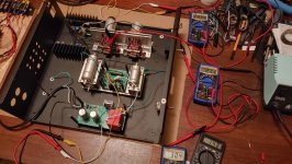
First power on of one channel with tube installed tonight and everything is looking good.
Raw DC output of 15.6V allowing for me to get 580-600mA and 2.1V for the filament.
Connected the B+ by way of Ale's cap multi board and on to Gyrator. Voltage at anode is 148V and reading 300mV at test point for 30mA.
This is using a hybrid of 6 diodes off the filament and then a series 3.6ohm to ground.
Attachments
That all sounds like a typical "solid state" stage, and 30mA is good for a 4P1L. In my own case I mostly listen to opera, classical and jazz so I have quite stringent demands for the tonality of voices and acoustic instruments. This caused me to abandon the gyrator solution in favour of a simple resistor load - purer and no glare at all. I used the combination of diodes and resistor for a short while because it was convenient, but once again abandoned it because of the same discomfort with an audible edge to the tone. This disappeared with a simple resistor in the cathode, using filament bias. I'm a massive experimenter, and have tried just about every version of a line stage, and I've ended up with no solid state apart from the filament regs for the DHTs.
However, with the 4P1L the demands of using 30mA current push up the B+ which might not be desirable. So I have tended to use valves which are comfortable at lower currents like 12-15mA. The 4P1L isn't - it sounds thin below about 25mA. So I moved to other DHTs. 2P29L is OK and quite transparent but there's better. 112A has a fuller tone but it's quite a boring valve. 26 can sound good - it's a nice valve especially on vocals. But if you're already at 1A for the filaments why not then go for a 47 at 1.5A. This has become the choice for my "daily" amp. The 10Y is better still if you can find any, but it's expensive. Still the best, though. So for an affordable DHT stage my choice goes to the 47. The 46 is also good. Again, I use it in filament bias with a resistor load. Pure sound, transparent, no glare at all.
If my primary listening was rock music I might find a gyrator and diodes in the cathode acceptable, but I never listen to rock music. For acoustic instruments I stick to resistors or otherwise a good plate choke. Always filament bias with Rod Coleman regs. .
Okay, so I would want to revive this thread a little bit: I scrambled every part that I needed to modify my e88cc heaphone amp, and Ive ended up with this: signal straight from ad1865 dac to 4p1l grid, loaded on Ale Moglia gyrators, with rc network in cathode (my bad I dont have colemans regulators and filament bias, just sigma11 low noise power supplies for the filament, and running the 4p1ls on 4.2 volts). Precision resistor and elna cerafine in cathode.
After this it is cap coupled (1uf k40y-9 russian pio) to mosfet IRF540 source follower and to my 35 ohm headphones. Follow the schematic.
Since the first notes playing I have been surprised with this preamp. Such a clarity and lots of emotions in the music. Crystal clear sound. Best sound Ive heard from my experiments with headphone amplifiers. Plus I have almost zero noise (I took several precautions to eliminate both power supply hum noise and high frequency noise). But the microphonics is a little problematic, yes. So far so good. The 4P1Ls really sing. I think about what modifications I can do or if I can try some other DHTs? Maybe 2P29L? Or I have a pair of old european E422 tubes (equivalents of telefunken re134).
That looks nice. If you want better than 4P1L I would use a type 26. However Ri is 7.5K so your source follower would have to do some work on that. With a gyrator you could look at the 01A as well. That's very nice.
The 2P29L is about the same level of sound as 4P1L. The 4P1L needs at least 25mA through it, 30mA better. 2P29L isn't so fussy.
The 2P29L is about the same level of sound as 4P1L. The 4P1L needs at least 25mA through it, 30mA better. 2P29L isn't so fussy.
- Home
- Amplifiers
- Tubes / Valves
- 4P1L DHT Line Stage